In-vehicle image display apparatus

a technology for displaying apparatuses and vehicles, applied in television systems, instruments, transportation and packaging, etc., can solve the problems of inability to have a correct understanding of the state of the surroundings of the vehicle, inability to have a correct understanding of the state of the surroundings, and inability to drive safely, so as to limit damage and limit the effect of collision damag

Inactive Publication Date: 2010-12-07
CASE PATENT INC
View PDF13 Cites 10 Cited by
  • Summary
  • Abstract
  • Description
  • Claims
  • Application Information

AI Technical Summary

Benefits of technology

[0009]According to the in-vehicle image display apparatus set forth in claim 1, the image representing the state of the surroundings of the vehicle is displayed in the window section of the vehicle. Thus, a driver can reliably understand the state of the surroundings of the vehicle. That is, the in-vehicle image display apparatus can be designed to display an image which is easy for the driver to view, for example by highlighting an image with a moving object, based on the detection results from the state detecting device. Thus, the driver can easily recognize contents of the image, that is, the state of the surroundings. Also, even an image representing the state far away from the vehicle can be displayed in the window section which is close to the driver. Thus, it is easy for the driver to view the image, and easy to understand the far away state. In this manner, the driver can reliably understand the state of the surroundings of the vehicle. Occurrence of an accident due to a delay in danger avoidance can be reliably inhibited. The in-vehicle image display apparatus can be designed such that the state detecting device detects at least an object present in the surroundings.
[0034]In the vehicle provided with the in-vehicle image display apparatus set forth in claim 12 or 13, if there is a condition that a collision with other vehicle in the surroundings is inevitable, a possibly collidable object except for the other vehicle is searched. If there is such an object, the vehicle is controlled to collide with the object. That is, a collision with other vehicle is avoided even though the vehicle collides with the object other than the other vehicle, to limit the damage. According to this in-vehicle image display apparatus, the damage by the collision can be limited to a minimum.

Problems solved by technology

That is, the driver is unable to have a correct understanding of the state of the surroundings of the vehicle.
Thus, there is a delay in risk aversion, which leads to an accident.
Also, as noted above, if there is low visibility by the weather or temporary decreased vision of the driver, the driver is unable to have a correct understanding of the state of the surroundings.
Risk of driving, that is, probability that an accident may occur, is increased.

Method used


Image

  • In-vehicle image display apparatus
  • In-vehicle image display apparatus
  • In-vehicle image display apparatus

Examples


first embodiment

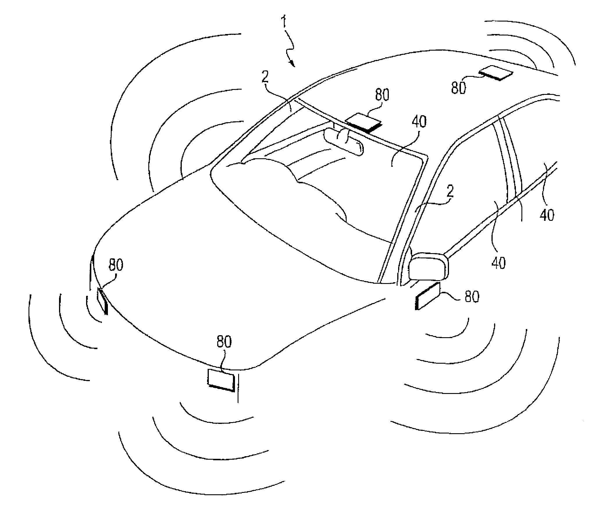
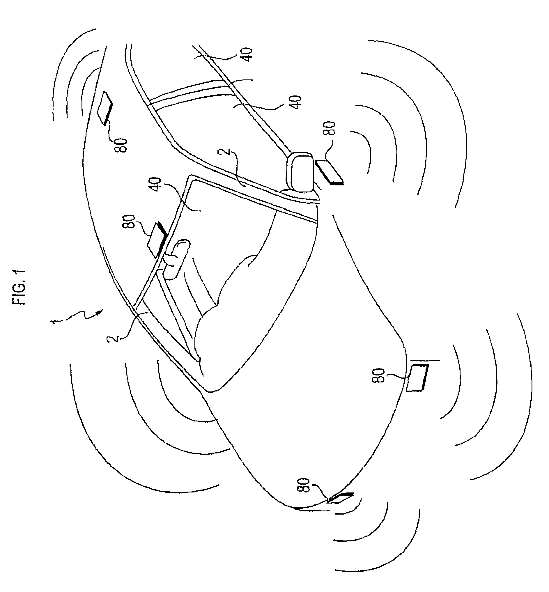
[0046]FIG. 1 is an appearance diagram showing an appearance of a vehicle 1 provided with an in-vehicle image display apparatus 5 (see FIG. 2) of the present embodiment. As shown in FIG. 1, a detecting unit 80 of the in-vehicle image display apparatus 5 for detecting the state of the surroundings of the vehicle 1 is provided at a plurality of positions outside the body of the vehicle 1. This detecting unit 80 detects the state of the surrounding scene, surrounding people, other vehicle (hereinafter, also referred to as other vehicle), obstruction and others, as the state of the surroundings of the vehicle 1. Although not shown in FIG. 1, an in-vehicle unit 90 (see FIG. 2) composing the in-vehicle image display apparatus 5 is provided inside the vehicle 1 aside from the detecting unit 80. Based on detection results from the detecting unit 80, an image representing the state of the surroundings of the vehicle 1 is generated by the in-vehicle unit 90.

[0047]Specifically, in the present e...

second embodiment

[0104]Now, the in-vehicle image display apparatus 5 of the second embodiment will be explained by way of FIGS. 7 and 8.

[0105]In the in-vehicle image display apparatus 5 of the present second embodiment in comparison with that of the first embodiment, the display glass panel 40 in the window section of the vehicle 1 is designed to be switched between a screen display mode functioning as a screen and the ordinary mode like an ordinary window. In the screen display mode, lights from inside and outside of the vehicle 1 are blocked. That is, the display glass panel 40 turns into a smoky state and functions as a screen. On the display glass panel 40 in a state of the screen display mode, an image is projected by a projector 45 (see FIG. 7).

[0106]Especially in the present second embodiment, an image is also displayed on the inside face of A-pillars 2 (see FIGS. 1 and 2) of the vehicle 1 regarded as a screen, other than the display glass panel 40 in the screen display mode. If an image of t...

third embodiment

[0109]Now, the in-vehicle image display apparatus 5 of the third embodiment will be explained by way of FIG. 9.

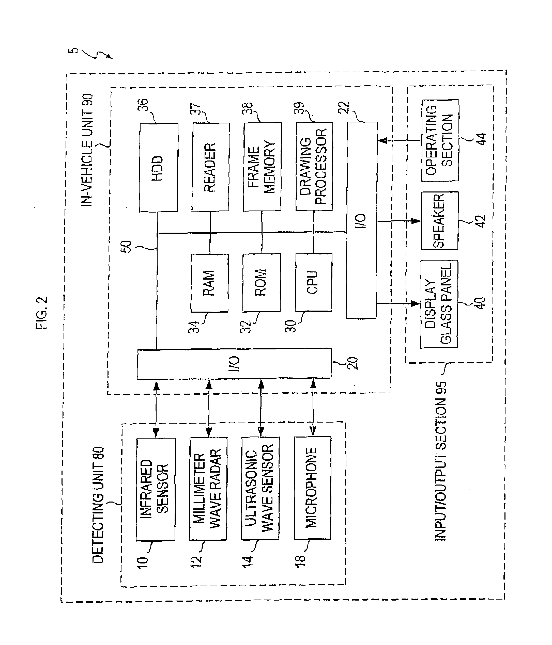
[0110]The in-vehicle image display apparatus 5 of the present third embodiment is different from that of the first embodiment in that a CCD camera 16 is used instead of the detecting unit 80. Also, in the in-vehicle unit 90, a CCD interface (hereinafter, referred to as CCD I / F) 24 is provided to exchange data with the CCD camera 16 instead of the I / O 20.

[0111]Imaging data (in other words, detection data) representing an image taken by the CCD camera 16 is transmitted to the in-vehicle unit 90 to be stored in the RAM 34 of the in-vehicle unit 90. The drawing processor 39 adds coloring data to the imaging data (detection data) stored in the RAM 34 to generate a computer graphic image in the step of S430 in FIG. 4. An image taken by the CCD camera 16 may be directly displayed on the display glass panel 40.

[0112]According to the in-vehicle image display apparatus 5 of the prese...


PUM


Abstract

An in-vehicle image display apparatus for use in a vehicle is provided which includes: a state detecting device that detects a state of surroundings of the vehicle; a display device that is provided at least in an entire front window section of the vehicle and capable of displaying information over the entire window section; an image generating device that generates image data for displaying an image of the surroundings of the vehicle on the display device based on detection results from the state detecting device; and a display control device that makes the display device display an image represented by the image data generated by the image generating device.

Description

TECHNICAL FIELD[0001]This invention relates to an in-vehicle image display apparatus that displays an image in a window section of a vehicle of a bus, a taxi, a private car or the like.BACKGROUND ART[0002]One of the conventional causes for vehicle-related accidents such as an accident between vehicles, an accident between a vehicle and a passer-by, etc. is considered an oversight or a misjudgment by a driver on a passer-by, other vehicle, an obstruction or the like in the surroundings of the vehicle, for example due to low visibility by the weather (rain, snow, etc.) or temporary decreased vision of the driver by eyestrain and others. That is, the driver is unable to have a correct understanding of the state of the surroundings of the vehicle. Thus, there is a delay in risk aversion, which leads to an accident. To put it the other way around, if the driver can have a correct understanding of the state of the surroundings of the vehicle, an accident can be avoided.[0003]A conventiona...

Claims


Application Information

Patent Timeline
Patent Type & Authority Patents(United States)
IPC IPC(8): G08B5/00E03F5/04
CPCB60K35/00B60R1/00G02B27/01B60K2350/2013B60K2350/2052B60R2300/202B60R2300/205G02B2027/0138G02B2027/014Y02T10/84B60K2370/21B60K2370/334
Inventor KIDO, KAORU
Owner CASE PATENT INC
Why Eureka
Try Eureka