In-vehicle image display apparatus
a technology for displaying equipment and vehicles, which is applied in the field of vehicles with image display equipment, can solve the problems of inability of drivers to have a correct understanding of the state of the surroundings of vehicles, and achieve the effect of limiting damage and limiting damage by collisions
- Summary
- Abstract
- Description
- Claims
- Application Information
AI Technical Summary
Benefits of technology
Problems solved by technology
Method used
Image
Examples
first embodiment
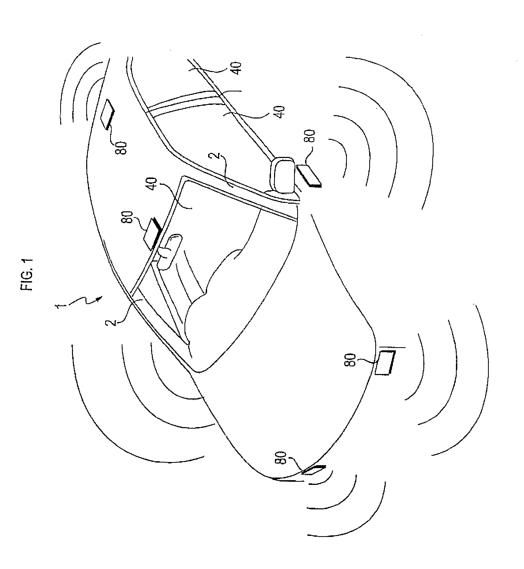
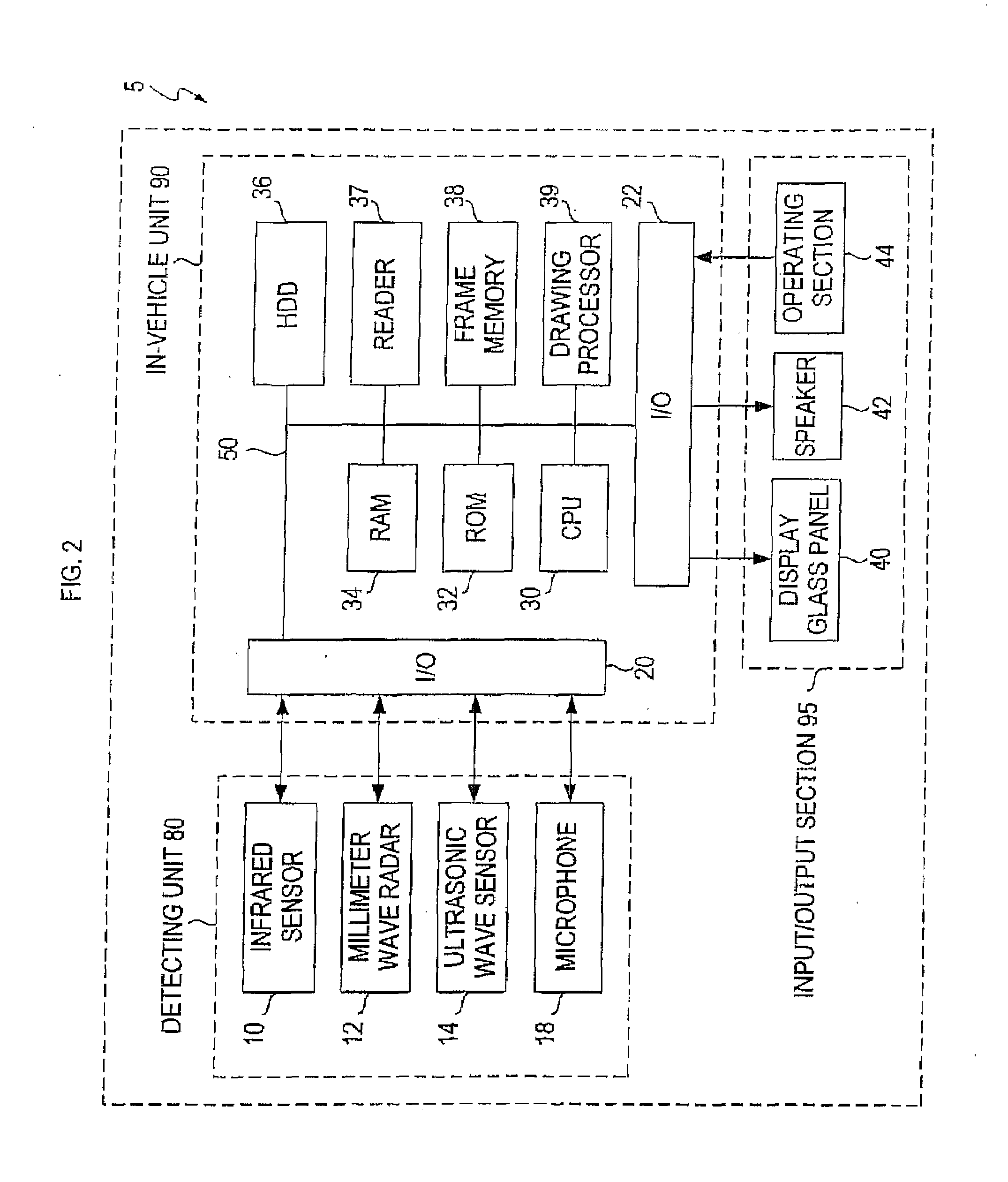
[0047]FIG. 1 is an appearance diagram showing an appearance of a vehicle 1 provided with an in-vehicle image display apparatus 5 (see FIG. 2) of the present embodiment. As shown in FIG. 1, a detecting unit 80 of the in-vehicle image display apparatus 5 for detecting the state of the surroundings of the vehicle 1 is provided at a plurality of positions outside the body of the vehicle 1. This detecting unit 80 detects the state of the surrounding scene, surrounding people, other vehicle (hereinafter, also referred to as other vehicle), obstruction and others, as the state of the surroundings of the vehicle 1. Although not shown in FIG. 1, an in-vehicle unit 90 (see FIG. 2) composing the in-vehicle image display apparatus 5 is provided inside the vehicle 1 aside from the detecting unit 80. Based on detection results from the detecting unit 80, an image representing the state of the surroundings of the vehicle 1 is generated by the in-vehicle unit 90.
[0048]Specifically, in the present e...
second embodiment
[0105]Now, the in-vehicle image display apparatus 5 of the second embodiment will be explained by way of FIGS. 7 and 8.
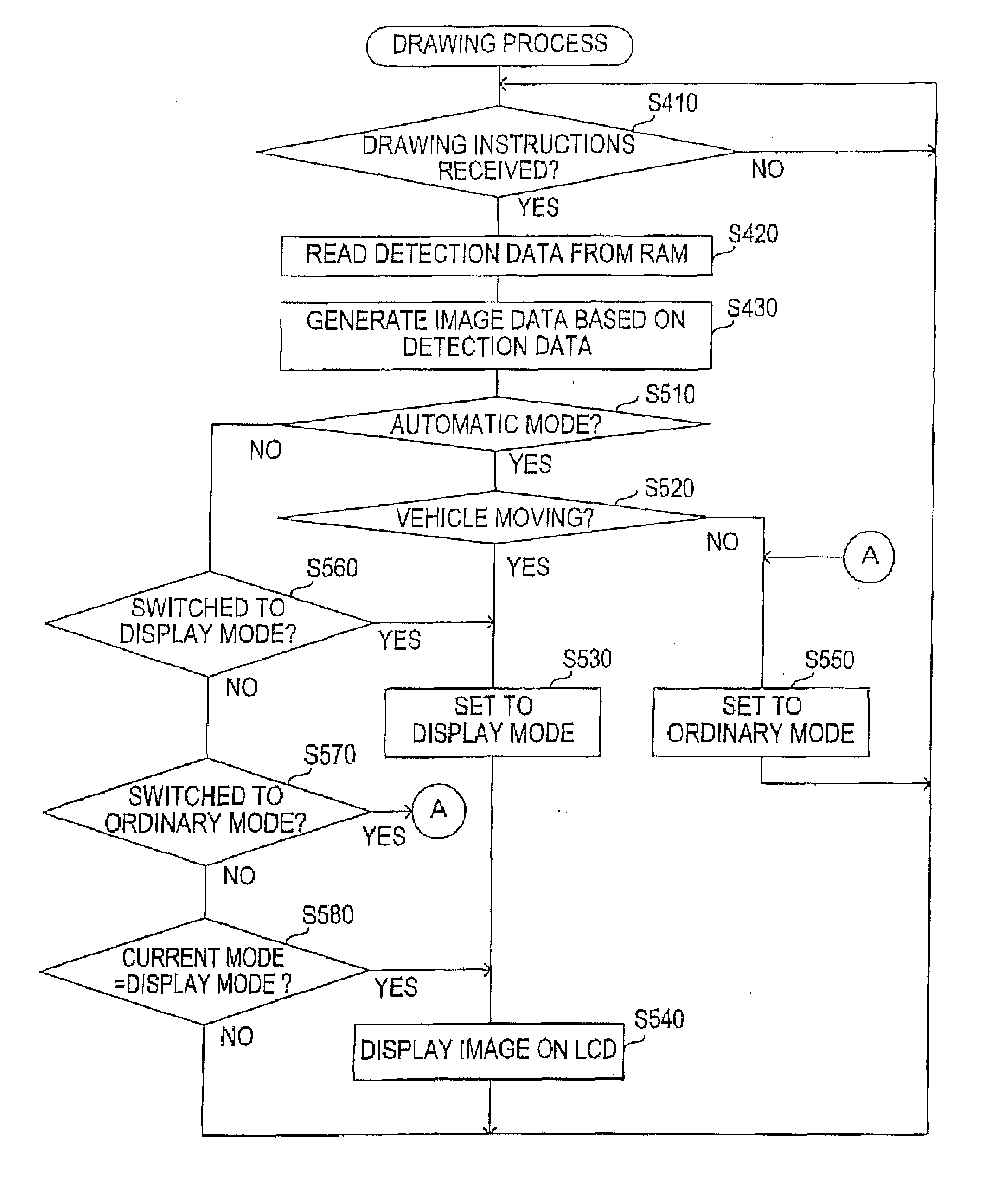
[0106]In the in-vehicle image display apparatus 5 of the present second embodiment in comparison with that of the first embodiment, the display glass panel 40 in the window section of the vehicle 1 is designed to be switched between a screen display mode functioning as a screen and the ordinary mode like an ordinary window. In the screen display mode, lights from inside and outside of the vehicle 1 are blocked. That is, the display glass panel 40 turns into a smoky state and functions as a screen. On the display glass panel 40 in a state of the screen display mode, an image is projected by a projector 45 (see FIG. 7).
[0107]Especially in the present second embodiment, an image is also displayed on the inside face of A-pillars 2 (see FIGS. 1 and 2) of the vehicle 1 regarded as a screen, other than the display glass panel 40 in the screen display mode. If an image of t...
third embodiment
[0110]Now, the in-vehicle image display apparatus 5 of the third embodiment will be explained by way of FIG. 9.
[0111]The in-vehicle image display apparatus 5 of the present third embodiment is different from that of the first embodiment in that a CCD camera 16 is used instead of the detecting unit 80. Also, in the in-vehicle unit 90, a CCD interface (hereinafter, referred to as CCD I / F) 24 is provided to exchange data with the CCD camera 16 instead of the I / O 20.
[0112]Imaging data (in other words, detection data) representing an image taken by the CCD camera 16 is transmitted to the in-vehicle unit 90 to be stored in the RAM 34 of the in-vehicle unit 90. The drawing processor 39 adds coloring data to the imaging data (detection data) stored in the RAM 34 to generate a computer graphic image in the step of S430 in FIG. 4. An image taken by the CCD camera 16 may be directly displayed on the display glass panel 40.
[0113]According to the in-vehicle image display apparatus 5 of the prese...
PUM
 Abstract
Description
Claims
Application Information
 - R&D
- Intellectual Property
- Life Sciences
- Materials
- Tech Scout
- Unparalleled Data Quality
- Higher Quality Content
- 60% Fewer Hallucinations
Browse by: Latest US Patents, China's latest patents, Technical Efficacy Thesaurus, Application Domain, Technology Topic, Popular Technical Reports.
© 2025 PatSnap. All rights reserved.Legal|Privacy policy|Modern Slavery Act Transparency Statement|Sitemap|About US| Contact US: help@patsnap.com


