Orthodontic anchor

a technology for orthodontic anchors and anchors, applied in the field of orthodontic anchors, can solve the problems of pain in the implant, neighboring mucous membranes, and wearers' feelings of physical disorder or foreign sensation, so as to avoid excessive damage to minimize the bore size of the anchor, and save the mandible or maxilla bon

Inactive Publication Date: 2007-08-21
YASUNORI HOTTA
View PDF11 Cites 38 Cited by
  • Summary
  • Abstract
  • Description
  • Claims
  • Application Information

AI Technical Summary

Benefits of technology

[0016]The size of the anchor bore can be minimized to avoid damaging the mandible or maxilla bone excessively and can be formed in the mandible or maxilla bone using a boring device. Each tissue opening is eventually filled in with mucous membrane tissues that are in contact with the tissue openings after the orthodontic anchor is embedded to provide additional anchorage. The anchor plate is placed between the mandible or maxilla bone and the covering mucous membrane.
[0017]The mucous membrane tissues that eventually fill in the openings can provide as much as two thirds of the entire anchorage. Therefore, the anchorage required of the protrusion and the tiny anchor bore in the mandible or maxilla bone in combination can be as little as one third of the entire anchorage required for effective orthodontic use. The smallness of the anchor bore greatly contributes to conservation of the mandible or maxilla bone without substantive damage thereto.
[0018]The orthodontic anchor of the present invention facilitates easy use and provides long lasting reliable anchorage for correction of malocclusion with limited damage to the mandible or maxilla bone and covering mucous membrane tissues.
[0019]The orthodontic anchor of the present invention also allows three-dimensional freedom of manipulation.

Problems solved by technology

Generally, the implant is painful to patients not only during the implanting processes but also after the implanting processes as well as during the implant removal processes.
In addition, the implantation and removal of the implant damages the mandible or maxilla bone and neighboring mucous membranes.
Conventional implants also cause feelings of physical disorder or foreign sensation in wearers.
However, the screw holes of the miniplate are interconnected, and no means are provided to specifically connect any wiring to the plate; thus, such a plastic surgery device is not suitable for use in orthodontic applications.
An orthodontic implant may conventionally be secured to the mandible or maxilla bone with a miniature screw or screws, which do not provide sufficient anchorage because the mandible or maxilla bone is not solid enough to maintain the miniature screw or screws for prolonged use.
When the anchorage is not sufficient, a gap may form between the hole of the mandible or maxilla bone and the gap that might be created and may lead to an infection.

Method used


Image

  • Orthodontic anchor
  • Orthodontic anchor
  • Orthodontic anchor

Examples


first embodiment

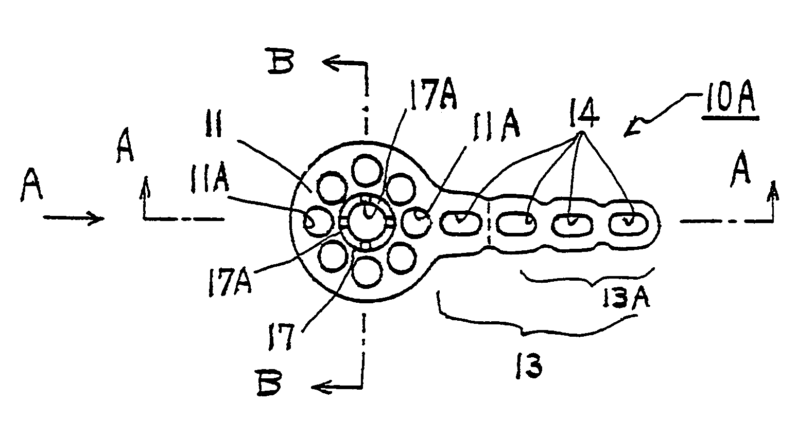
[0051]FIG. 1 shows an orthodontic anchor 10A according to the present invention. The orthodontic anchor 10A is comprised of an anchor plate 11 and an engagement plate 13. The anchor plate 11 and the engagement plate 13 are integrated into a single piece. The anchor plate 11 is provided with a protrusion 17 and eight tissue openings 11 A, and the engagement plate 13 is provided with four engagement openings 14, of which the proximal or base opening 14 or void is used to help provide flexibility to the engagement plate 13 while the distal three openings 14 within the range 13A are exposed into the oral cavity (shown in FIGS. 12 and 13) for use to provide engagement with teeth biasing means (shown in FIGS. 16 and 17).

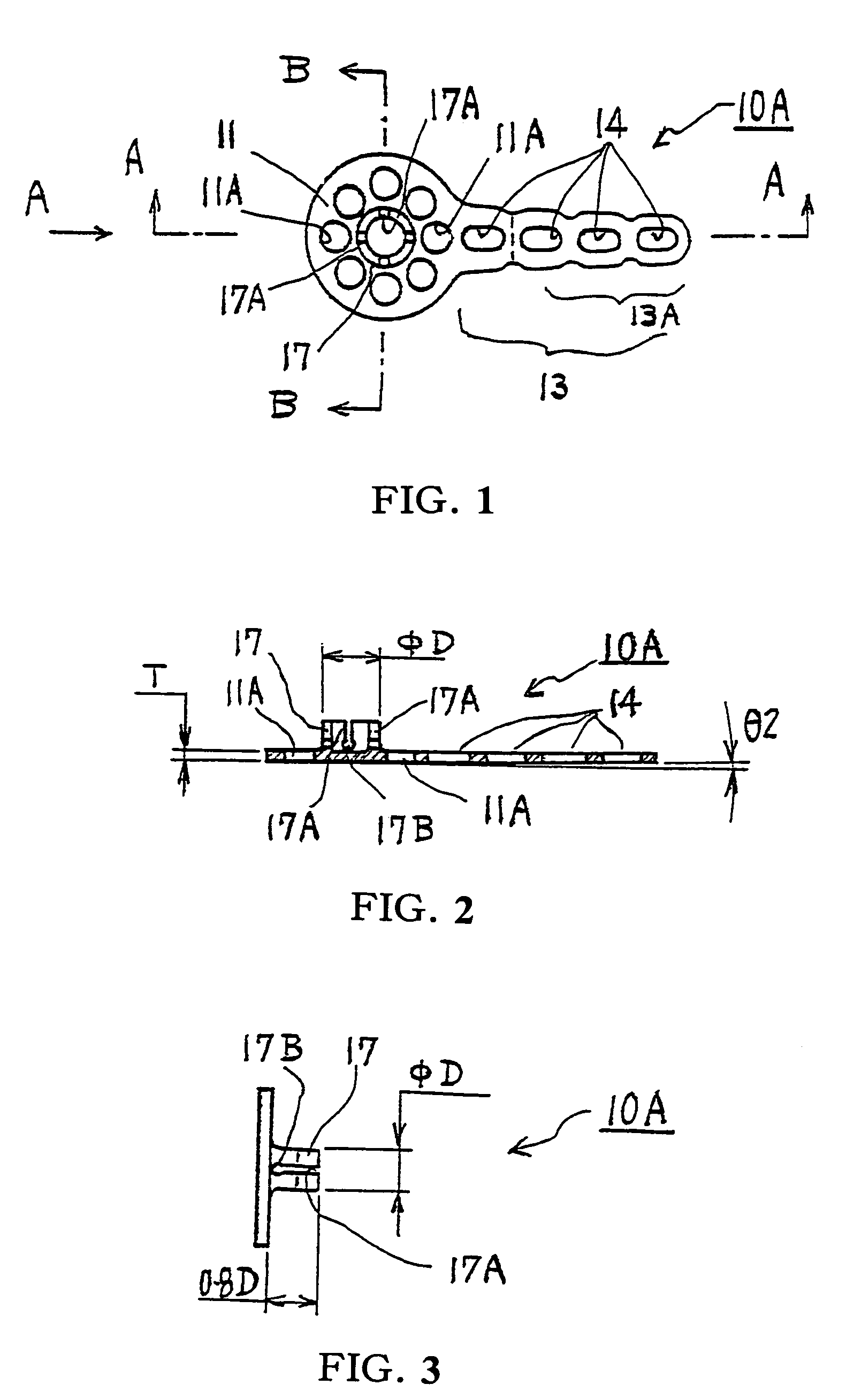
[0052]FIG. 2 is a sectional view of the orthodontic anchor 10A sectioned along line A-A shown in FIG. 1. The orthodontic anchor 10A is shown having a thickness “T” and taper “θ2”. The protrusion 17 is shown having an outside diameter “D”.

[0053]FIG. 3 is a view as seen from...

second embodiment

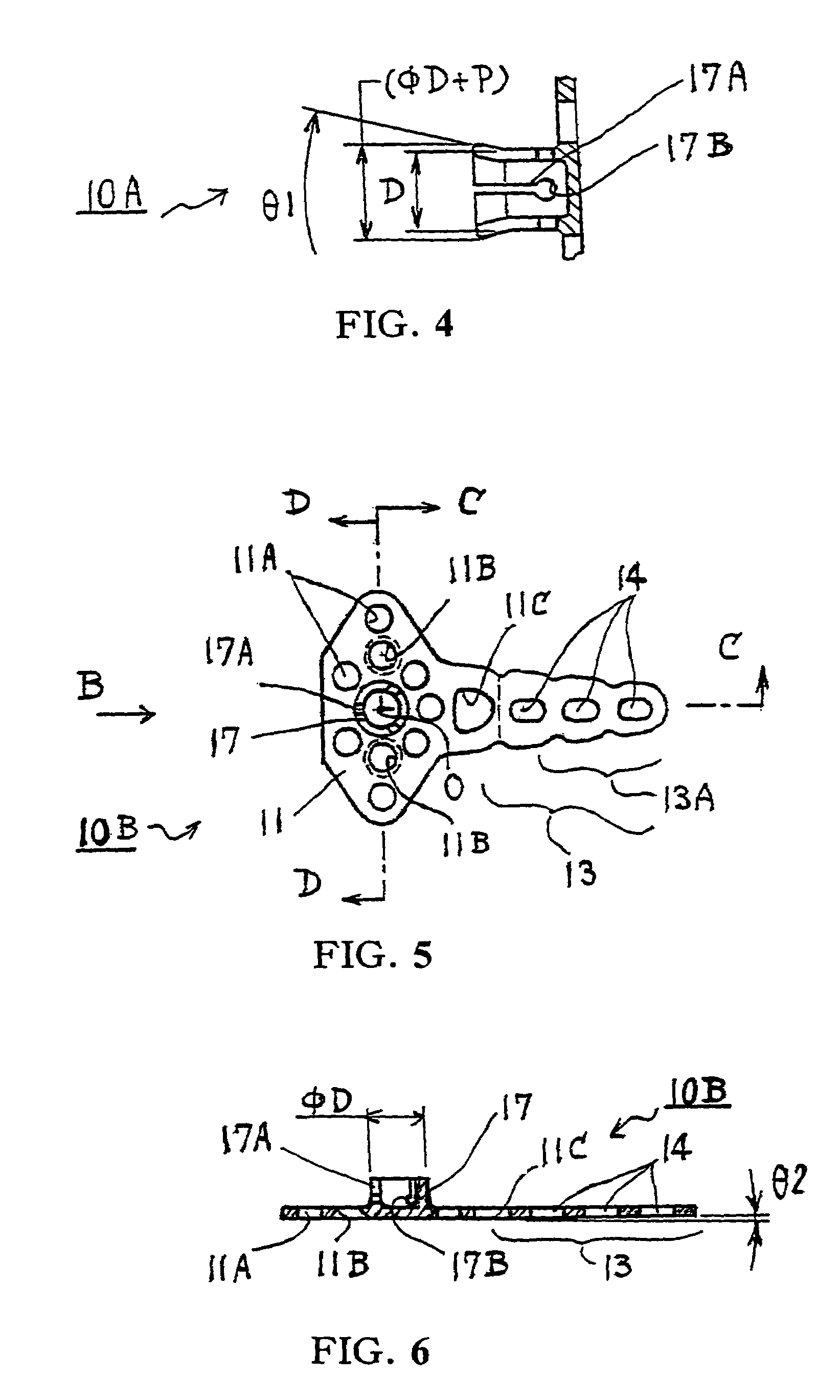
[0055]FIG. 5 shows another orthodontic anchor 10B according to the present invention. The anchor plate 11 is not circular, but is instead formed as a deformed eclipse. The anchor plate 11 is provided with a protrusion 17 whose wall is separated into three axially extending portions with axially extending slits 17A each having a clearance 17B. The anchor plate 11 is also provided with seven tissue openings 11A. It is possible to have more tissue openings 11A because the anchor plate 11 is large enough to accommodate more. The anchor plate 11 is additionally provided with two tapered edge holes, or screw openings 11B, to accept screws. A screw (not shown in the figure) is inserted into each screw opening 11B to be screwed into the mandible or maxilla bone (not shown) to provide additional anchorage. As such, an according to FIG. 5, orthodontic anchor is capable of providing greater anchorage than the orthodontic anchor shown in FIG. 1.

[0056]The engagement plate 13 of the orthodontic a...

third embodiment

[0060]FIG. 9 shows another orthodontic anchor 10C according to the present invention. This orthodontic anchor 10C has two oppositely positioned engagement plates 13, which are secured to the upper jaw bone (not shown). This orthodontic anchor 10C is suitable for use as shown in FIG. 16.

[0061]FIG. 10 is a sectional view of the orthodontic anchor 10C sectioned along line E-O-E shown in FIG. 9.

[0062]FIG. 11(A) shows an example boring device 15 or hole saw comprised of a cutter end 15A, base portion 15B, cylinder 15C and holes 15D. The boring device 15 is connected to a motor means and used like an end mill to prepare a bore 20 in the mandible or maxilla bone 1. FIG. 11(B) is a view as seen from side “C” of the boring device 15 shown in FIG. 11(A). FIG. 11(C) is a view as seen from side “D” of the boring device 15 shown in FIG. 11(A).

[0063]In the following are described processes to use the orthodontic anchor 10.

[0064]FIG. 12 shows in a schematic view a first state of use of the orthodo...


PUM


Abstract

An orthodontic anchor is disclosed. The orthodontic anchor has an anchor plate to be embedded between the mandible or maxilla bone and the covering mucous membrane and an engagement plate that remains exposed in the oral cavity. The anchor plate includes a protrusion and tissue openings. The protrusion is to be integrated with a bore prepared in the mandible or maxilla bone and the tissue openings are to be filled in with tissues to provide anchorage. The engagement plate includes engagement openings which are used to engage with a ligament device for correction of malocclusion.

Description

FIELD OF THE INVENTION[0001]This invention relates to an orthodontic anchor that can be used for correcting of malocclusions.BACKGROUND TECHNOLOGY[0002]There exists a variety of orthodontic therapies and devices for rectifying of malocclusions. Generally, such therapies require the use of teeth biasing means and anchoring means.[0003]Conventionally, such anchorage may be provided either internally or externally. When provided within the mouth, the anchorage is typically provided by utilizing the molar teeth or using bone implants. “Implant Orthodontics / Dental Laser” (SUZUKI, Junji; CHIYODA SHOBO; 27 Jul. 2002) teaches the use of implants that are partially embedded in the mandible or maxilla bone to provide anchorage for an orthodontic device. JP Patent Application Laid-Open Publication No. 2001-187071 teaches use of an orthodontic device having a base and an extension. The base is screwed to the mandible or maxilla bone to provide the required anchorage.[0004]Conventionally, when a...

Claims


Application Information

Patent Timeline
Patent Type & Authority Patents(United States)
IPC IPC(8): A61C3/00A61C8/00A61C7/00
CPCA61C7/00A61C8/0096
Inventor HOTTA, YASUNORI
Owner YASUNORI HOTTA
Why Eureka
Try Eureka