X-ray diagnostic imaging system with a plurality of coded markers

a diagnostic imaging and coded marker technology, applied in the field of x-ray diagnostic imaging system, can solve the problems of small number of markers that can be evaluated and the accuracy of position measurement in such systems may be limited

Active Publication Date: 2011-04-19
ZIEHM IMAGING
View PDF22 Cites 164 Cited by
  • Summary
  • Abstract
  • Description
  • Claims
  • Application Information

AI Technical Summary

Problems solved by technology

Additionally, only a small number of markers can be evaluated if the position detection system is unfavorably positioned relative to the X-ray diagnostic imaging system.
The accuracy of the position measurement may be limited in such systems.

Method used


Image

  • X-ray diagnostic imaging system with a plurality of coded markers
  • X-ray diagnostic imaging system with a plurality of coded markers
  • X-ray diagnostic imaging system with a plurality of coded markers

Examples


Embodiment Construction

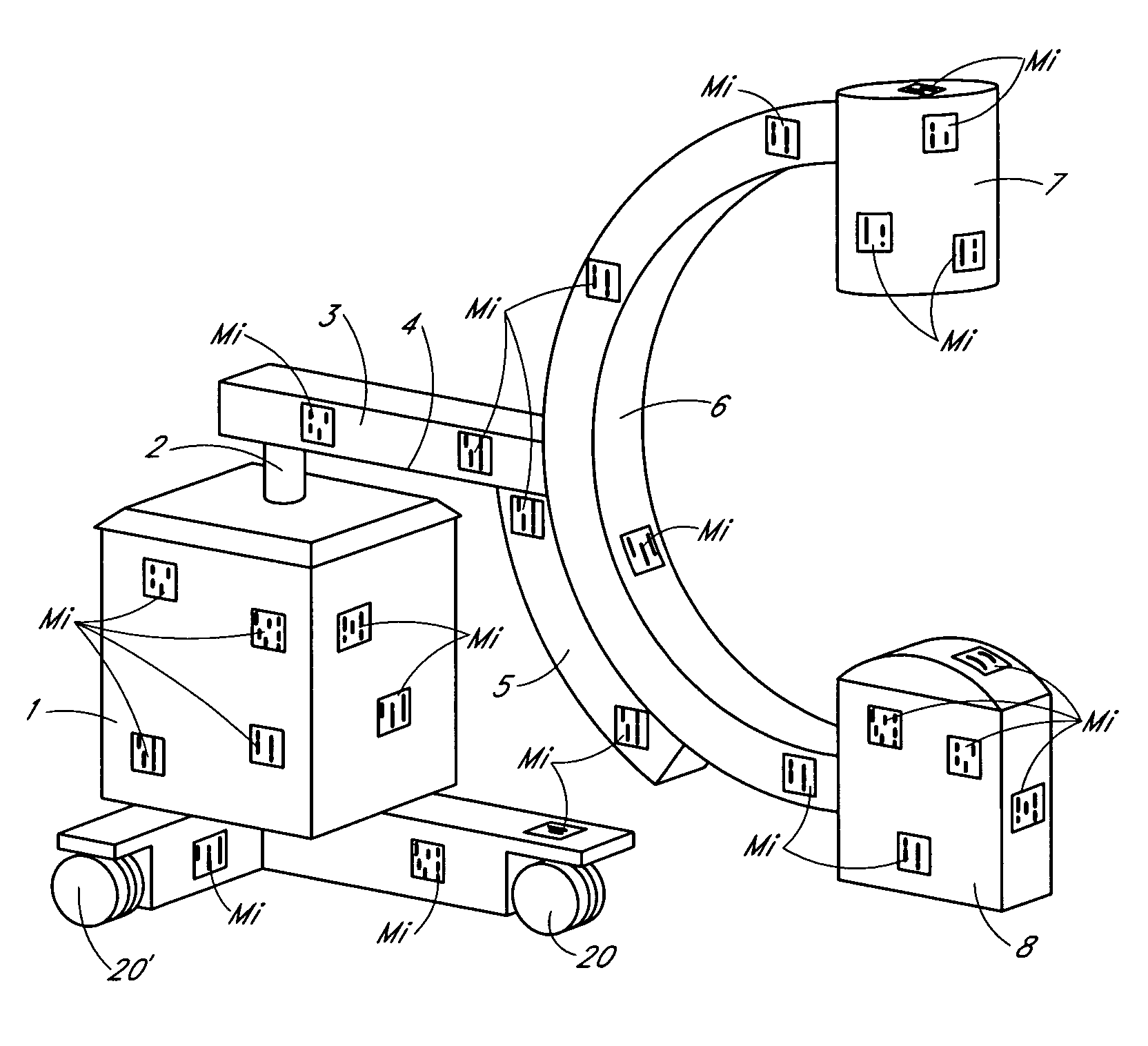
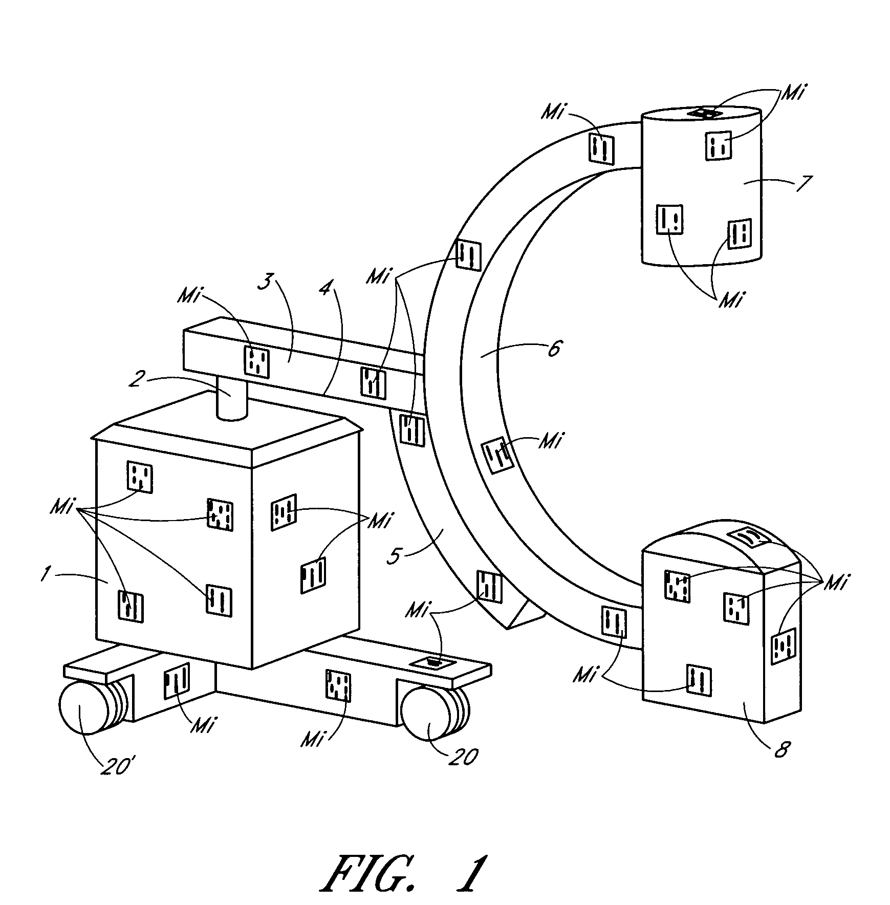
[0028]FIG. 1 schematically illustrates an embodiment of a mobile X-ray diagnostic imaging system comprising a cart 1 that can be moved along the floor on rollers 20, 20′. The imaging system comprises a C-arm 6 that is mounted to the cart 1 with C-arm mount 5. The C-arm 6 can be adjusted in multiple ways. The C-arm 6 is movable along its circumference about a center of the C-arm 6. The C-arm mount 5 is supported on a horizontally displaceable horizontal guide 3 with a pivot bearing 4, which permits the C-arm 6 to be pivoted about a horizontal axis. The horizontal guide 3 is supported on a column 2, which can be adjusted in height and rotated about the vertical axis of the column 2. An X-ray source 8 and an X-ray receiver 7 are disposed on opposing ends of the C-arm 6.

[0029]In the embodiment illustrated in FIG. 1, a plurality of coded markers Mi is distributed over surfaces of various components of the X-ray diagnostic imaging system. For example, as shown in FIG. 1, the markers Mi ma...


PUM


Abstract

Embodiments of an X-ray diagnostic imaging system comprise a plurality of coded 2D and / or 3D markers associated with surfaces of system components. The position and coding of at least some of the coded markers can be determined by a position detection system. In some embodiments, a coded marker is assigned a reference point having a known position on the surface of the system component. The positions of the system components in space can be calculated based at least in part on a reference point network determined from the position of the individual reference points measured with the position detection system. In some embodiments, the coded markers represent information with a data matrix code (DMC).

Description

CROSS-REFERENCE TO RELATED APPLICATIONS[0001]This application claims the right of priority under 35 U.S.C. §119(a)-(d) to German Patent Application No. DE 10 2007 021 185.8, filed May 5, 2007, the entire disclosure of which is hereby incorporated by reference herein and made part of this specification.BACKGROUND[0002]1. Field[0003]The disclosure relates generally to an X-ray diagnostic imaging system with a marker arrangement on surfaces of system components and methods for determining positions of the system components.[0004]2. Description of the Related Art[0005]Medical interventions involving living subjects are increasingly performed using navigation assistance provided by a navigation system. In some navigation systems, a surgical instrument is guided by means of a position detection system relative to a tissue region of the subject undergoing treatment. Navigation assistance is of particular interest in body regions that cannot be visually inspected by the surgeon, such as whe...

Claims


Application Information

Patent Timeline
Patent Type & Authority Patents(United States)
IPC IPC(8): G01D18/00
CPCA61B6/12A61B6/4441A61B6/547A61B19/52A61B2019/5445A61B2019/5238A61B2019/5255A61B2019/5265A61B2019/5437A61B19/5244A61B34/20A61B90/36A61B2034/2055A61B2034/2065A61B2090/376A61B2090/3937A61B2090/3945
Inventor DEHLER, JUERGEN
Owner ZIEHM IMAGING
Why Eureka
Try Eureka