Remote control system

a remote control and control system technology, applied in the field of control equipment, can solve problems such as the question of on which the control of manipulation should be based

Inactive Publication Date: 2011-05-03
FUNAI ELECTRIC CO LTD
View PDF12 Cites 8 Cited by
  • Summary
  • Abstract
  • Description
  • Claims
  • Application Information

AI Technical Summary

Benefits of technology

[0009]The present invention was made to solve the above-described problems. An object of the present invention is to provide a remote control system capable of controlling equipment by properly making selection between control based on the manipulation on hand and control based on the external manipulation.

Problems solved by technology

Here, if the manipulation on hand and the external manipulation are simultaneously performed, the problem arises as to on which manipulation control should be based.

Method used


Image

  • Remote control system
  • Remote control system
  • Remote control system

Examples


embodiment 1

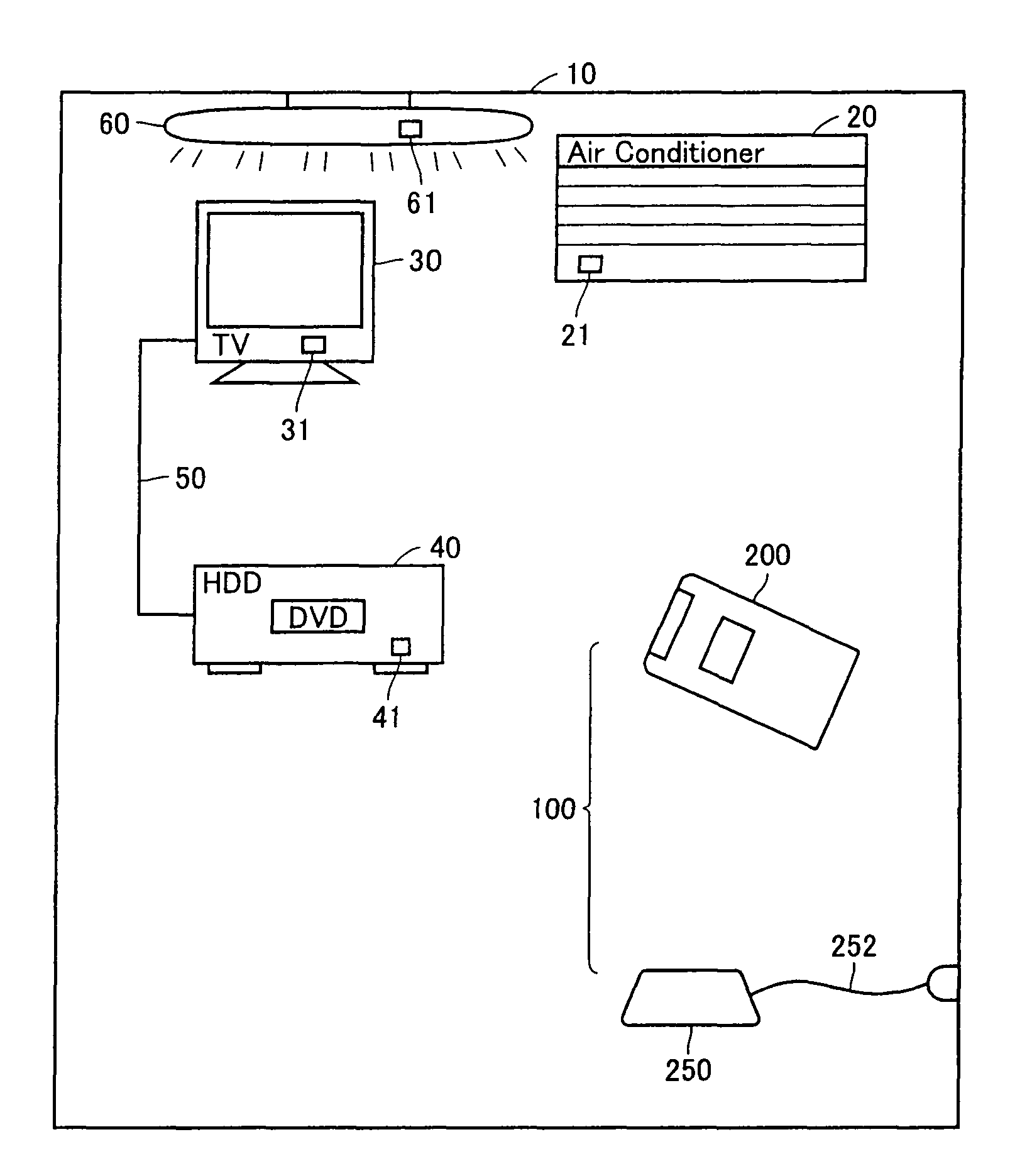
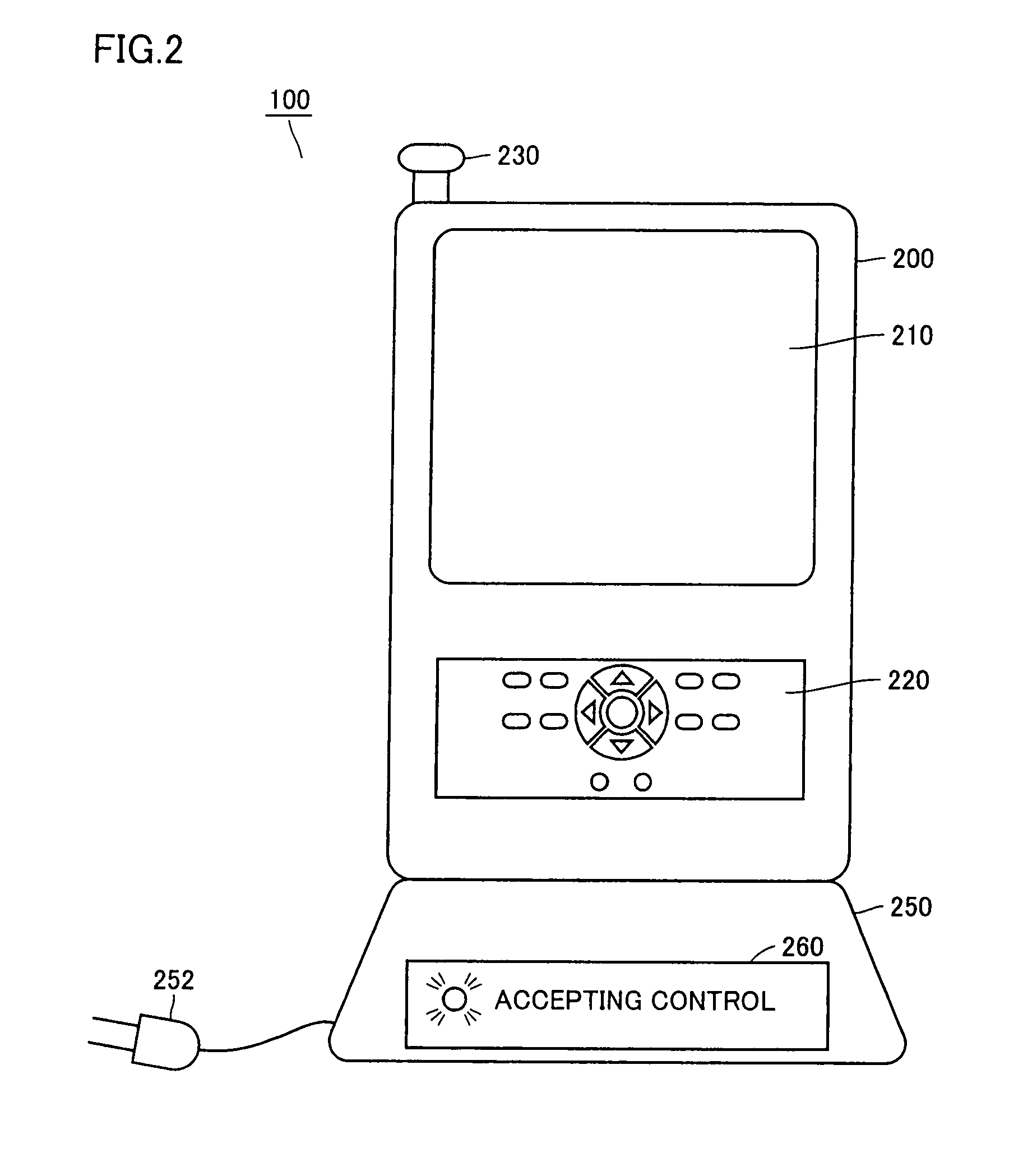
[0046]With reference to FIG. 1, a manner of use of a remote control system 100 according to an embodiment of the present invention will be described. FIG. 1 shows arrangement of remote control system 100 according to Embodiment 1 of the present invention and each piece of control target equipment controlled by remote control system 100. Remote control system 100 is used in a room 10.

[0047]In room 10, an air conditioner 20, a television 30, a hard disk recorder 40 connected to television 30, and an illumination device 60 are provided. Television 30 and hard disk recorder 40 are connected to each other via a cable 50. Air conditioner 20 includes a light-receiving portion 21 receiving an infrared signal for controlling an operation of air conditioner 20. Television 30 includes a light-receiving portion 31 receiving an infrared signal for controlling an operation of television 30. Hard disk recorder 40 includes a light-receiving portion 41 receiving an infrared signal for controlling an...

embodiment 2

[0096]Embodiment 2 of the present invention will be described in the following. The remote control system according to the present embodiment is different from Embodiment 1 described previously in mechanically detecting placement of the remote controller in the cradle.

[0097]Specifically, referring to FIG. 9, a remote controller 900 according to the present embodiment has a recess portion 902 formed at a junction surface with a cradle 950. On the other hand, cradle 950 has a projection portion 952 formed, corresponding to recess portion 902. At a coupling portion of recess portion 902 and projection portion 952, a circuit is configured such that the circuit closes when the recess portion and the projection portion are coupled to each other. Alternatively, the circuit may open on such an occasion. In any case, connection between remote controller 900 and cradle 950 can be detected.

[0098]FIG. 10 shows a configuration of a placement detection circuit provided in remote controller 900. A...

embodiment 3

[0100]Embodiment 3 of the present invention will be described in the following. The remote controller according to the present embodiment is different from each embodiment described previously in a function to display a control state of the equipment or a state of the remote controller. It is noted that the remote controller according to the present embodiment has the same hardware configuration as that of the remote controller according to each embodiment previously described. A newly added function is attained, for example, by adding a program module for display processing by CPU 410. As the functions of the hardware configuration are otherwise the same, description thereof will not be repeated.

[0101]With reference to FIG. 11, a control structure of a remote controller according to the present embodiment will be described. FIG. 11 is a flowchart illustrating a procedure of processing performed by CPU 410.

[0102]In step S1110, CPU 410 reads data from memory 450. The read data includ...


PUM


Abstract

Source of input of an instruction to a remote controller is switched between manipulation on hand and external manipulation. A remote controller includes an instruction input portion accepting input of an instruction for controlling equipment, a supply accepting portion accepting supply of power from a cradle, a charging portion, a power storage portion, a control portion controlling an operation of the remote controller, a storage portion, an infrared light emission portion, and a display portion. The control portion includes a placement detection portion detecting whether or not the remote controller is mounted on the cradle, a selection portion switching between sources of input of the instruction from the instruction input portion based on a result of detection by the placement detection portion, and a control signal generation portion generating a control signal for controlling the equipment.

Description

BACKGROUND OF THE INVENTION[0001]1. Field of the Invention[0002]The present invention relates to a technique to control equipment, and more particularly to a remote control system over a network.[0003]2. Description of the Background Art[0004]As to what is called a remote control device for controlling an operation of equipment, a remote control device permitting external manipulation over the network in addition to manipulation on hand has been known. The remote control device permits manipulation by a user holding the remote control device, that is, the manipulation on hand, and the manipulation based on control data obtained by reception of a signal transmitted via the Internet (hereinafter, referred to as “external manipulation”). Here, if the manipulation on hand and the external manipulation are simultaneously performed, the problem arises as to on which manipulation control should be based.[0005]As to the technique for externally controlling equipment, for example, Japanese P...

Claims


Application Information

Patent Timeline
Patent Type & Authority Patents(United States)
IPC IPC(8): G08C19/00G08B1/08B60R25/10G06F7/04H04N5/00H04Q9/00
CPCG08C17/02
Inventor ISHIMOTO, KOUICHIMASAKI, YASUO
Owner FUNAI ELECTRIC CO LTD
Why Eureka
Try Eureka