Signal coupling apparatus for power line communications using a three-phase four-wire power line

a signal coupling apparatus and power line technology, applied in the field of power line communication, can solve the problems of many disadvantages of power lines, delay, attenuation, noise, etc., and achieve the effect of improving the efficiency of power line communication and high data ra

Active Publication Date: 2011-07-12
KOREA ELECTROTECH RES INST
View PDF8 Cites 52 Cited by
  • Summary
  • Abstract
  • Description
  • Claims
  • Application Information

AI Technical Summary

Benefits of technology

[0011]The present invention is intended to solve the above-mentioned problems with the conventional signal coupling apparatus. One object of the present invention is to provide a signal coupling apparatus including an impedance-matching transformer and a transmission mode control circuit for high data rate power line communications on a high voltage distribution line, which can match an impedance of the high voltage distribution line and change transmission modes, thereby improving the efficiency of power line communications.
[0012]Another object of the present invention is to provide a signal coupling apparatus including an impedance-matching transformer and a transmission mode control circuit for high data rate power line communications on a high voltage distribution line, wherein the impedance-matching transformer includes at least two transformers connected in series and can match various impedances of high voltage power lines or distribution lines, thereby reducing signal loss.
[0015]Since the signal coupling apparatus according to the present invention includes an impedance-matching transformer to provide impedance-matching and a transmission mode control circuit to change transmission modes, the efficiency of power line communications can be improved.
[0016]Also, since the signal coupling apparatus according to the present invention can match various impedances of high voltage power lines or distribution lines, using at least two transformers, signal loss can be reduced.
[0017]Also, since the signal coupling apparatus according to the present invention can provide various transmission modes using a transmission mode control circuit, an optimal high voltage distribution path according to communication conditions can be obtained.

Problems solved by technology

Accordingly, when such power lines are used for communications, the power lines have many disadvantages, such as attenuation, noise, delay, etc.
However, since the conventional technique requires a separate impedance matching apparatus as well as the signal coupling apparatus for power line communications, there are difficulties in installation and management.

Method used


Image

  • Signal coupling apparatus for power line communications using a three-phase four-wire power line
  • Signal coupling apparatus for power line communications using a three-phase four-wire power line
  • Signal coupling apparatus for power line communications using a three-phase four-wire power line

Examples


Embodiment Construction

[0029]The invention is described more fully hereinafter with reference to the accompanying drawings, in which exemplary embodiments of the invention are shown. This invention may, however, be embodied in many different forms and should not be construed as limited to the exemplary embodiments set forth herein. Like reference numerals in the drawings denote like elements.

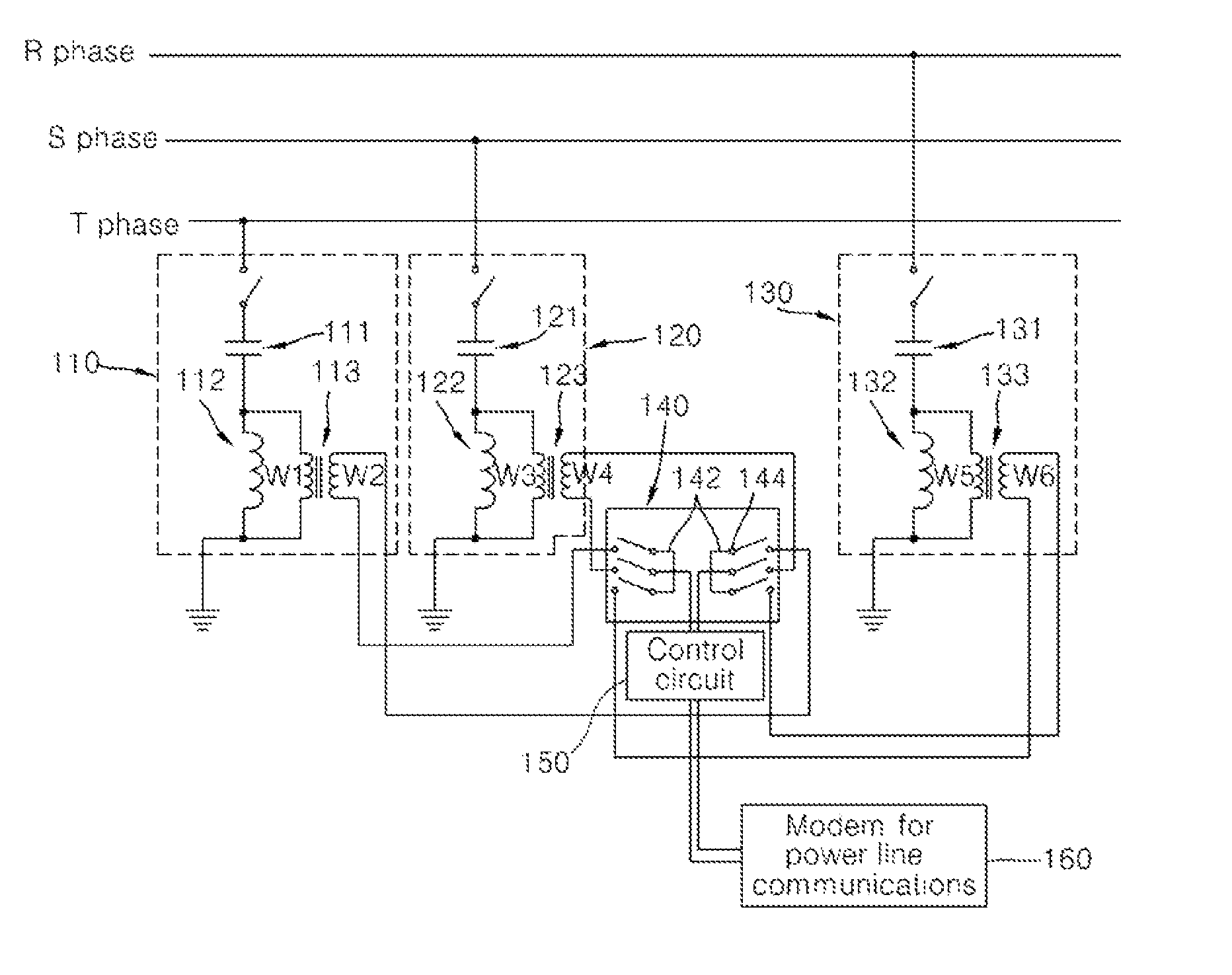
[0030]Hereinafter, a signal coupling apparatus including an impedance-matching transformer and a transmission mode control circuit for high data rate power line communications on a high voltage distribution line will be described in detail with reference to FIGS. 1 through 7.

[0031]In this specification, there is disclosed a new signal coupling apparatus for high data rate power line communications via a high voltage distribution line in a three-phase four-wire power line configuration. The signal coupling apparatus includes at least two transformers connected in series to match the impedance of a high voltage power li...


PUM


Abstract

A signal coupling apparatus for power line communications includes an impedance matching transformer and a transmission mode control circuit for high data rate power line communications on a three-phase four-wire distribution line. Therefore, it is possible to improve the efficiency of power line communications, to minimize signal loss, and to construct an optimal high voltage distribution path.

Description

CROSS-REFERENCE TO RELATED APPLICATION[0001]This application claims the benefit of Korean Patent Application No. 10-2007-0119992 filed on Nov. 23, 2007 with the Korean Intellectual Property Office, the disclosure of which is incorporated herein by reference.BACKGROUND OF THE INVENTION[0002]1. Field of the Invention[0003]The present invention relates to power line communications, and more particularly, to a signal coupling apparatus for power line communications using a three-phase four-wire power line.[0004]2. Description of the Related Art[0005]In general, power line communications are used to transmit communication signals, for example, digital data signals whose frequency is in the range from several hundreds of kHz to several dozens of MHz, over a power line or to a distribution line. In the power line communication technology, a communication signal transmitted through a power line is extracted by a high pass filter.[0006]In particular, the power line communication technology i...

Claims


Application Information

Patent Timeline
Patent Type & Authority Patents(United States)
IPC IPC(8): H04B3/54
CPCH04B3/56H04B2203/5425H04B2203/5466H04B3/54
Inventor CHOI, SUNG SOOLEE, JAE JOKIM, KWAN-HO
Owner KOREA ELECTROTECH RES INST
Why Eureka
Try Eureka