Electronically controlled tow hitch assembly

a tow hitch and electronic control technology, applied in the direction of towing devices, vehicle components, transportation and packaging, etc., can solve the problems of difficult assembly of the tow hitch, the ball mount is stolen, and the trailer is coupled to the hitch ball, so as to achieve the effect of safe and convenient tow operation

Inactive Publication Date: 2011-09-13
VISSER DIRK
View PDF5 Cites 7 Cited by
  • Summary
  • Abstract
  • Description
  • Claims
  • Application Information

AI Technical Summary

Benefits of technology

[0006]It is the object of the present invention to provide means whereby there is automatic control of the securing and release of assemblies of the kind referred to and to eliminate any play of the towball.SUMMARY OF THE INVENTION
[0010]Still further features of the invention provide for maximum engagement of the cam to lock the connector to the locking unit and allow engagement of a safety pin in the locking shaft.
[0016]To unlock the connector from the locking unit, the safety pin can be pulled out and held out for a period of time, such as three seconds, which will activate a roller switch, which in turn activates the controller to unlock the locking shaft. Requiring that the safety pin be removed from the aperture of the locking shaft for a period of time prevents the accidental unlocking of the connector.
[0019]All of these features of the invention discussed above contribute to the safety and ease of the operation of the tow hitch assembly.

Problems solved by technology

A problem with conventional tow hitches is that for various reasons the ball mount and the receiver are removably secured to each other.
In some instances it also leads to theft of a ball mount, hitch ball and a trailer coupled to the hitch ball.
A further problem with conventional tow hitches is that the assembly of the tow hitch is difficult due to misalignment of the flange and receiver.

Method used


Image

  • Electronically controlled tow hitch assembly
  • Electronically controlled tow hitch assembly
  • Electronically controlled tow hitch assembly

Examples


Embodiment Construction

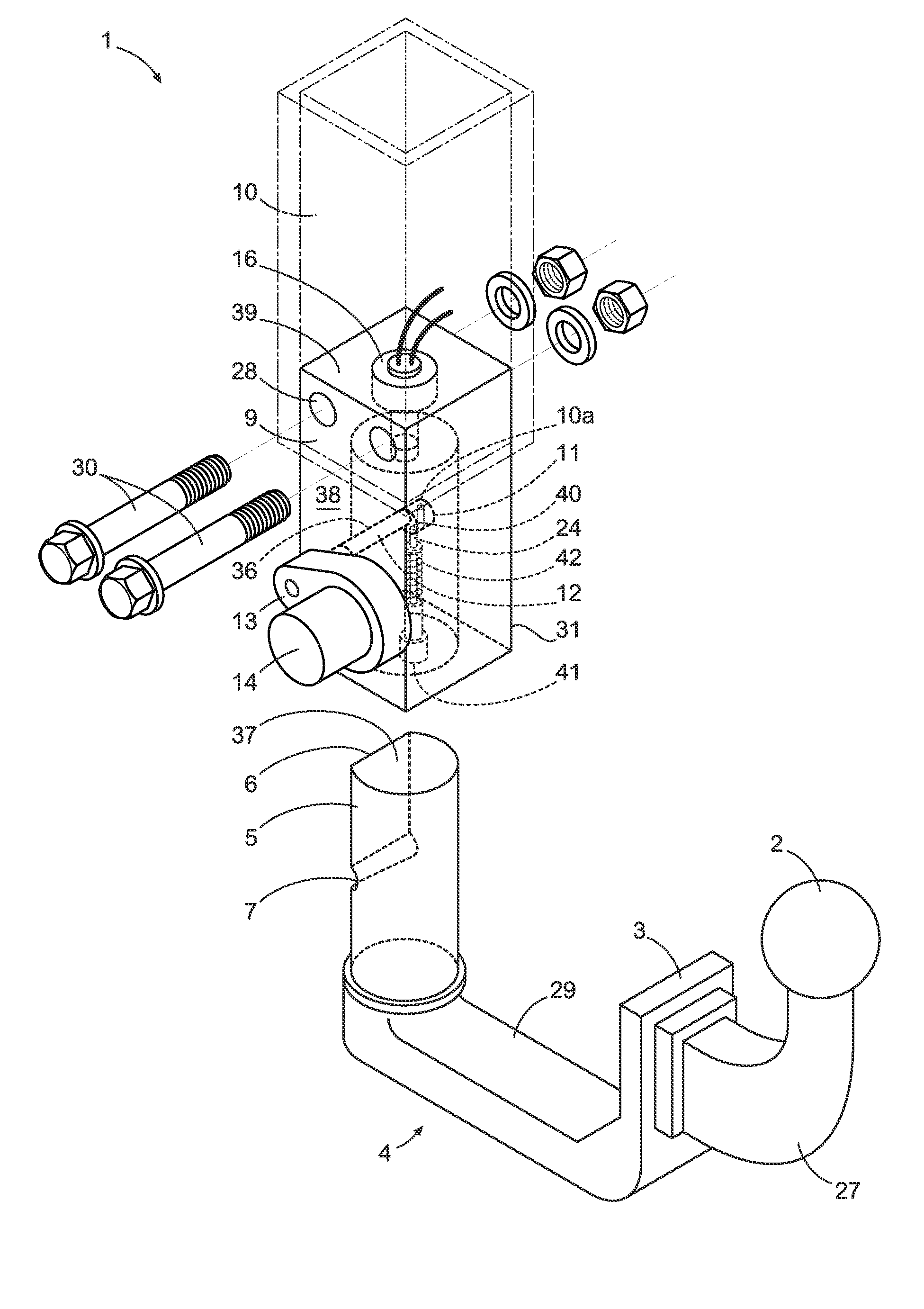
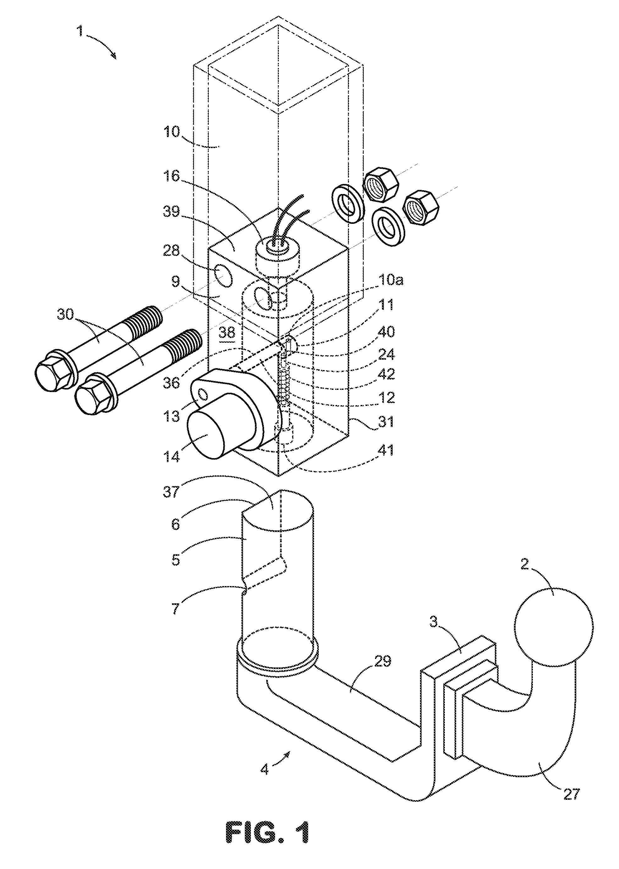
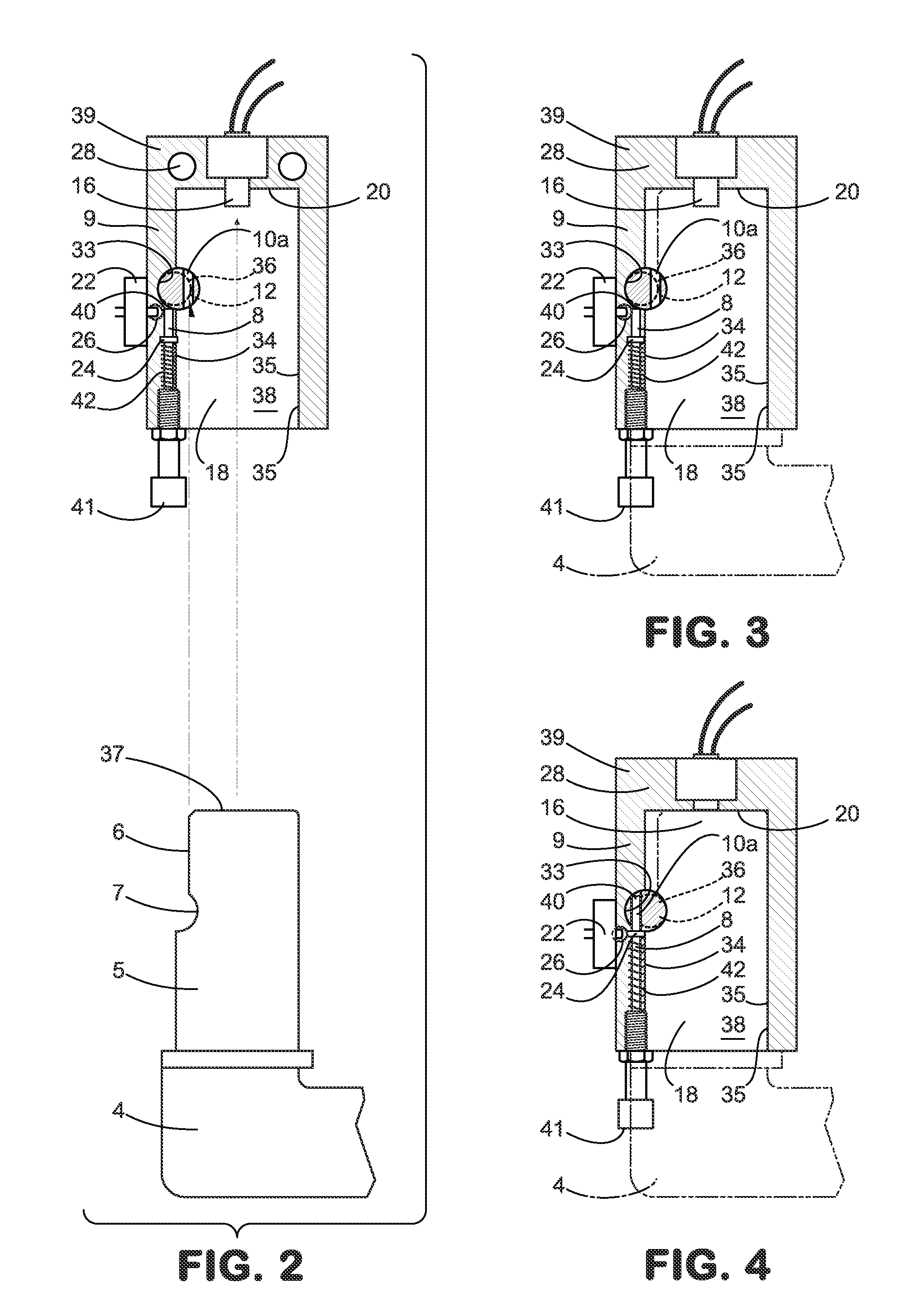
[0025]Turning now descriptively to the drawings, in which similar reference characters denotes similar elements throughout the several views, the figures illustrate the present invention. With regard to the referenced numerals used the following numbering is used throughout the various drawing figures.

[0026]

PARTS LIST 1. Tow Hitch Assembly 2. Tow Hitch Ball 3. Angled Face Plate 4.Flange or Ball Mount 5. Angled Connector 6. Flattened Face 7. Groove in Connector 8. Safety Pin 9. Locking Unit10. Harness10(a).Transverse Aperture in Locking Shaft11. Locking Shaft12. Eccentric Section of Locking Shaft13. Gearbox14. Electric Motor16. Activation Switch18. Receiving Aperture in Locking Unit20.Top of Locking Unit22.Roller Switch24.Shoulder of Safety Pin26.Sensor of Roller Switch27.Tow Hitch Holder28.Bolt Apertures29.Base30.Bolts33.Groove in Wall34.Wall35.Wall36.Cam on Eccentric Section of Locking Shaft37.Top of Connector38.Side of Locking Unit40.End of Safety Pin41.Knob42.Spring

DETAILED DESCR...


PUM


Abstract

An electronically controlled tow hitch assembly for a vehicle is provided which has a controller for locking and unlocking the assembly. The assembly has a locking unit with a receiving aperture into which a connector attached to a flange for holding a load or trailer is inserted. The locking unit has a locking shaft that extends through the aperture of the unit and passes through a groove in the wall of the aperture and an aligned groove in the connector for locking. An electric motor with a reduction gearbox is utilized to lock and unlock the connector from the locking unit. A spring loaded safety pin is used for locking the locking shaft with the tip of the safety pin entering the aperture and locking the locking shaft in position. The locking unit has an activation switch that determines when the connector has been fully inserted into the unit.

Description

CROSS-REFERENCE TO RELATED APPLICATION[0001]This application claims priority to corresponding U.S. provisional application entitled, “Electronically Controlled Tow Hitch Assembly,” having Ser. No. 61 / 110,647, filed Nov. 3, 2008, which is entirely incorporated herein by reference.FIELD OF THE INVENTION[0002]This invention relates to an electronically controlled tow hitch assembly for use with motor vehicles. This electronically controlled tow hitch assembly can be electronically connected and disconnected from the vehicle to improve safety and ease in performing these operations.BACKGROUND OF THE INVENTION[0003]Tow hitches such as those fitted on motor vehicles and the like normally include a hitch receiver which is secured to the vehicle and which includes a ball mount and towball. A ball mount is securable to the receiver and a hitch ball is in turn securable to the ball mount.[0004]A problem with conventional tow hitches is that for various reasons the ball mount and the receiver ...

Claims


Application Information

Patent Timeline
Patent Type & Authority Patents(United States)
IPC IPC(8): B60D1/06
CPCB60D1/52B60D1/58
Inventor VISSER, DIRK
Owner VISSER DIRK
Why Eureka
Try Eureka