Suction air nozzle for a textile machine

a technology for textile machines and suction air nozzles, which is applied in the field of suction air nozzles for textile machines, can solve the problems of insufficient reliably tensioning of long yarn loops inside the suction air nozzles, lack of suction force, and inability to effectively control the tension of long yarn loops, so as to reduce the risk of knot formation, stable positioning of yarn loops, and adequate yarn tension

Inactive Publication Date: 2010-03-23
OERLIKON TEXTILE GMBH & CO KG
View PDF17 Cites 1 Cited by
  • Summary
  • Abstract
  • Description
  • Claims
  • Application Information

AI Technical Summary

Benefits of technology

[0018]The embodiment according to the invention of a suction air nozzle with a nozzle body, the clear cross section of which increases from an inlet opening in the axial direction to an end-side outlet opening, has various advantages. While the workstation is being run up to operating speed, the yarn excess produced is sucked in as a yarn loop, for example, which is pulled apart with increasing yarn length and this considerably reduces the risk of knot formation. At the same time, the yarn loop which is becoming wider also forms a larger engagement face for the reduced pressure flow, which leads to very stable positioning of the yarn loop in the suction air nozzle and therefore to adequate yarn tension.
[0019]It is provided in an advantageous embodiment that the enlargement of the clear cross section of the nozzle body takes place continuously. Such a continuous enlargement of the clear cross section leads to a very uniform increase in the effective holding force in the suction air nozzle, which has a positive effect on the yarn loop. In other words, the yarn strands of the yarn loop run, although they are loaded by a relatively large suction force, into the edge regions of the nozzle body in a manner which is gentle on the yarn.
[0020]Not only the clear cross section of the central region, which has parallel side walls, becomes continuously larger in the direction of the outlet opening of the nozzle body, but so, too, does the clear cross section of the edge regions. In particular, the continuous, clear increase in the clear cross section of the edge regions leads to a calming of the suction air flow in these regions with the result that the yarn strands of the sucked-in yarn loop run in a relatively gentle manner along the walls of the edge regions.
[0021]It is also provided in an advantageous configuration of the invention that the tubular edge regions run in a divergent manner in the direction of the outlet opening of the nozzle body. A configuration of this type leads to a continuous enlargement of the clear cross section of the central region of the nozzle body, which has a positive effect both on the receiving volume of the suction air nozzle and on the suction force acting on the yarn.

Problems solved by technology

The disadvantage in these known suction air nozzles is not only their lack of suction force, but, in these suction air nozzles, there is always the risk, despite an elongate cross section in the yarn running direction that the sucked-in yarn loop may become twisted or form knots which may appreciably disturb the operation of the workstations.
It was possible to slightly ameliorate the problem of knot formation in the case of long yarn loops by means of suction air nozzles, such as are known from German Patent Publications DE 28 02 913 A1 or DE 38 29 151 A1, but suction air nozzles of this type continue to have the disadvantage that, in particular long yarn loops inside the suction air nozzle are not adequately reliably tensioned because of lack of suction force or inadequate suction force distribution.

Method used


Image

  • Suction air nozzle for a textile machine
  • Suction air nozzle for a textile machine
  • Suction air nozzle for a textile machine

Examples


Embodiment Construction

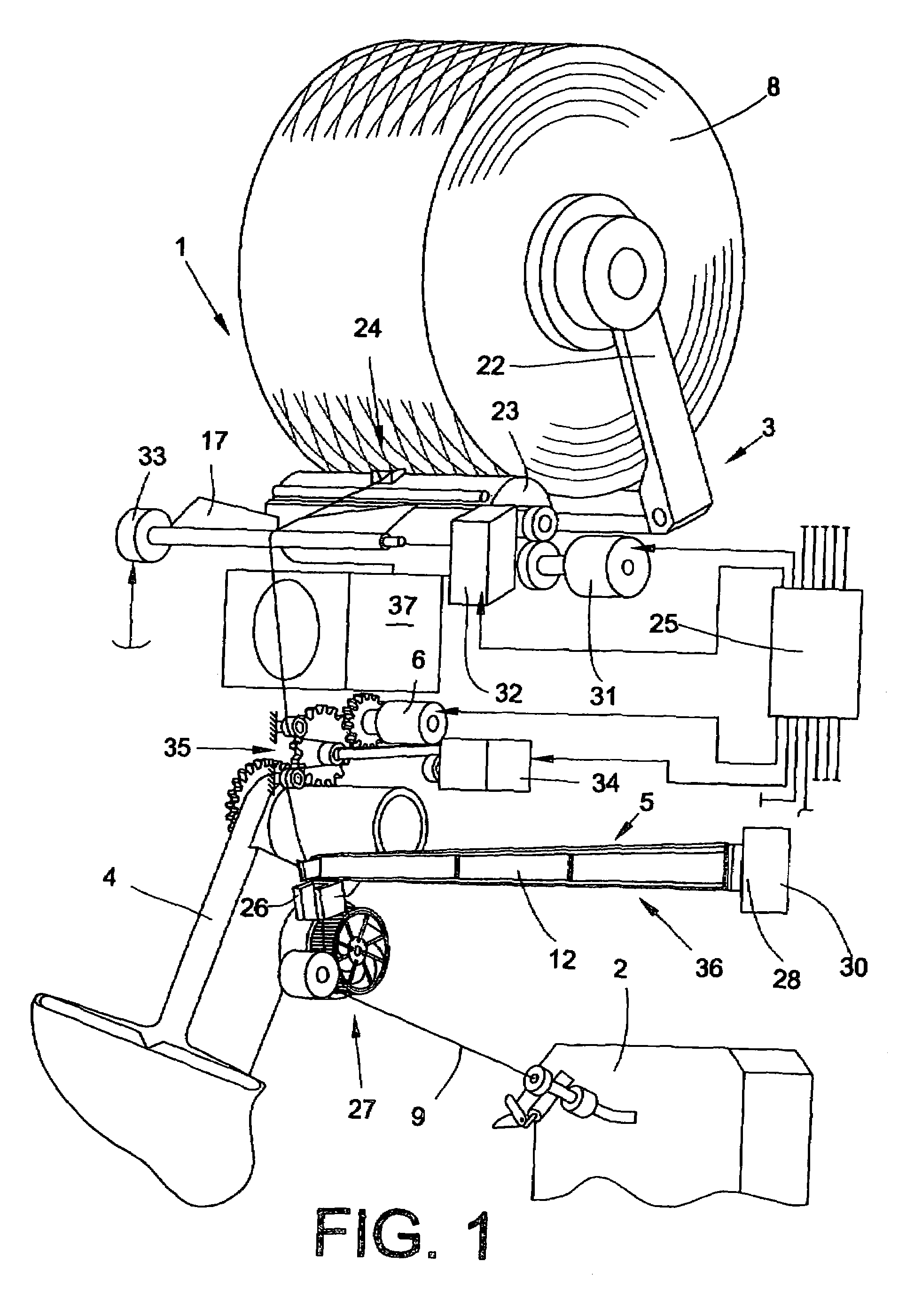
[0029]FIG. 1 shows a perspective view of a workstation, designated as a whole by the reference numeral 1, of an open-end rotor spinning machine. Workstations 1 of this type, as known, have a large number of workstation components which allow the production of a yarn 9 and the production of a cross-wound bobbin 8. Such workstations, for example, have an open-end spinning device 2 and a winding device 3.

[0030]Furthermore, workstations of this type have a yarn draw-off mechanism 27, which takes over the drawing off of the yarn 9 from the open-end spinning device 2 during regular spinning operation and also, during repiecing, ensures the return of the yarn end of the yarn 9 returned from the cross-wound bobbin 8 into the open-end spinning device 2.

[0031]The winding mechanism 3 itself consists, as indicated in FIG. 1, of a creel 22 for the rotatable holding of a cross-wound bobbin 8, a drive drum 23 which can preferably be driven by means of a reversible single drive 31, and a yarn trave...


PUM

PropertyMeasurementUnit
lengthaaaaaaaaaa
widthaaaaaaaaaa
tensionaaaaaaaaaa

Abstract

A suction air nozzle for a textile machine for storing a yarn length of a running yarn passing the nozzle opening. The nozzle has an elongate nozzle body, with a clear cross section having a narrower width in the region of its central longitudinal axis than in its tube-like edge regions. The nozzle further has an inlet opening, which has its largest width in the yarn running direction. The clear cross section of the nozzle body of the suction air nozzle increases from the inlet opening of the nozzle body in the axial direction to an end-side outlet opening.

Description

CROSS-REFERENCES TO RELATED APPLICATIONS[0001]This application claims the benefit of German patent application 10 2005 055 717.1, filed Nov. 23, 2005, herein incorporated by reference.BACKGROUND OF THE INVENTION[0002]The invention relates to a suction air nozzle for a textile machine for storing a yarn length of a running yarn passing the nozzle opening.[0003]Suction air nozzles of this type have been known for a long time in conjunction with spinning machines or winding machines or the service units associated with these textile machines and are described in numerous patent applications.[0004]Suction air nozzles of this type are used, for example, to keep the yarn tension constant during the winding operation or are used, for example, in spinning machines to store the temporarily occurring yarn excess when running the workstations up to operating speed and to supply it successively to the winding device of the relevant workstation.[0005]A textile machine is described in German Pate...

Claims


Application Information

Patent Timeline
Patent Type & Authority Patents(United States)
IPC IPC(8): D01H4/50
CPCB65H51/205D01H13/104D01H13/12B65H2701/31
Inventor PREUTENBORBECK, MAXIMILIANOEHRL, WILHELMSCHELTER, DETLEF
Owner OERLIKON TEXTILE GMBH & CO KG
Why Eureka
Try Eureka