

Morcellator with detachable handle
a morcellator and handle technology, applied in the field of surgical devices and methods, can solve the problems of affecting the patient's recovery, and affecting the recovery of patients, so as to reduce the trauma of patients and reduce the use of instruments
- Summary
- Abstract
- Description
- Claims
- Application Information
AI Technical Summary
Benefits of technology
Problems solved by technology
Method used
Image

Examples
Embodiment Construction
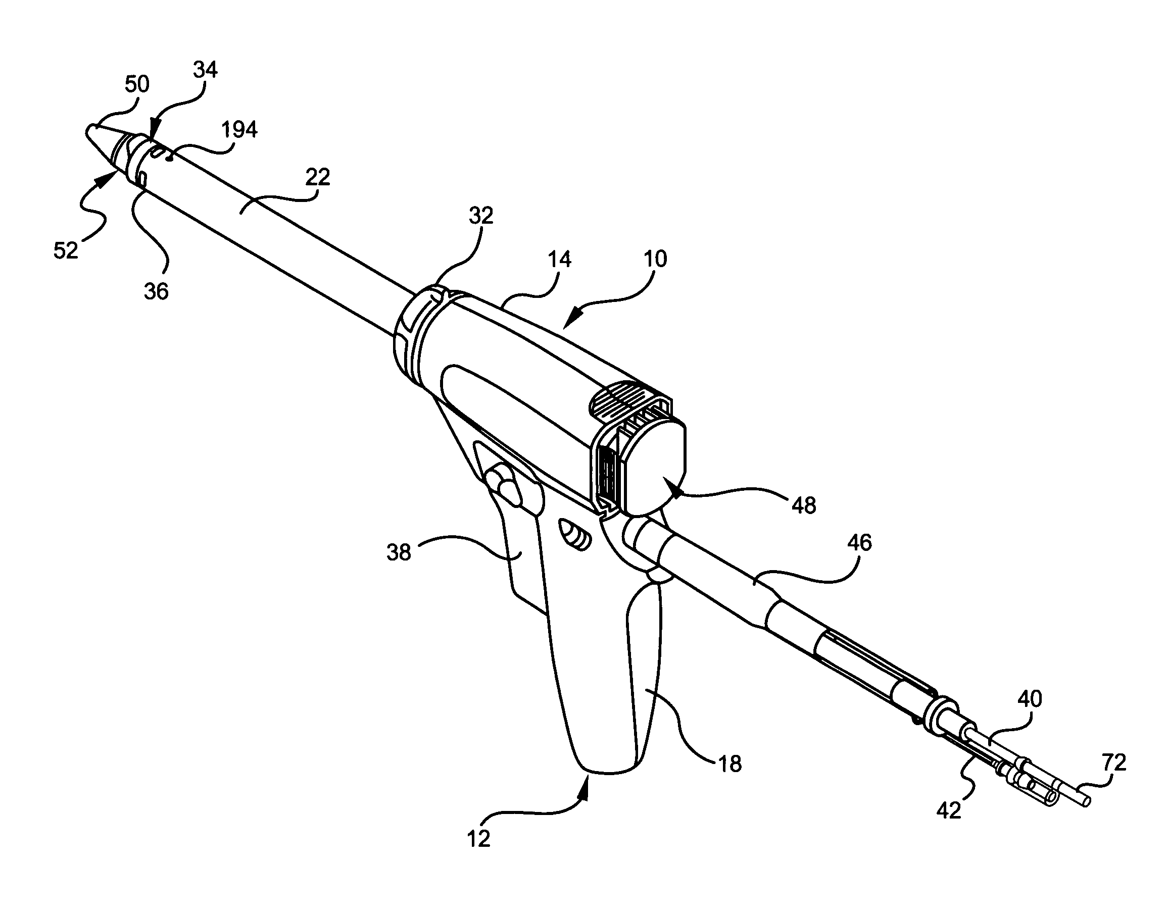
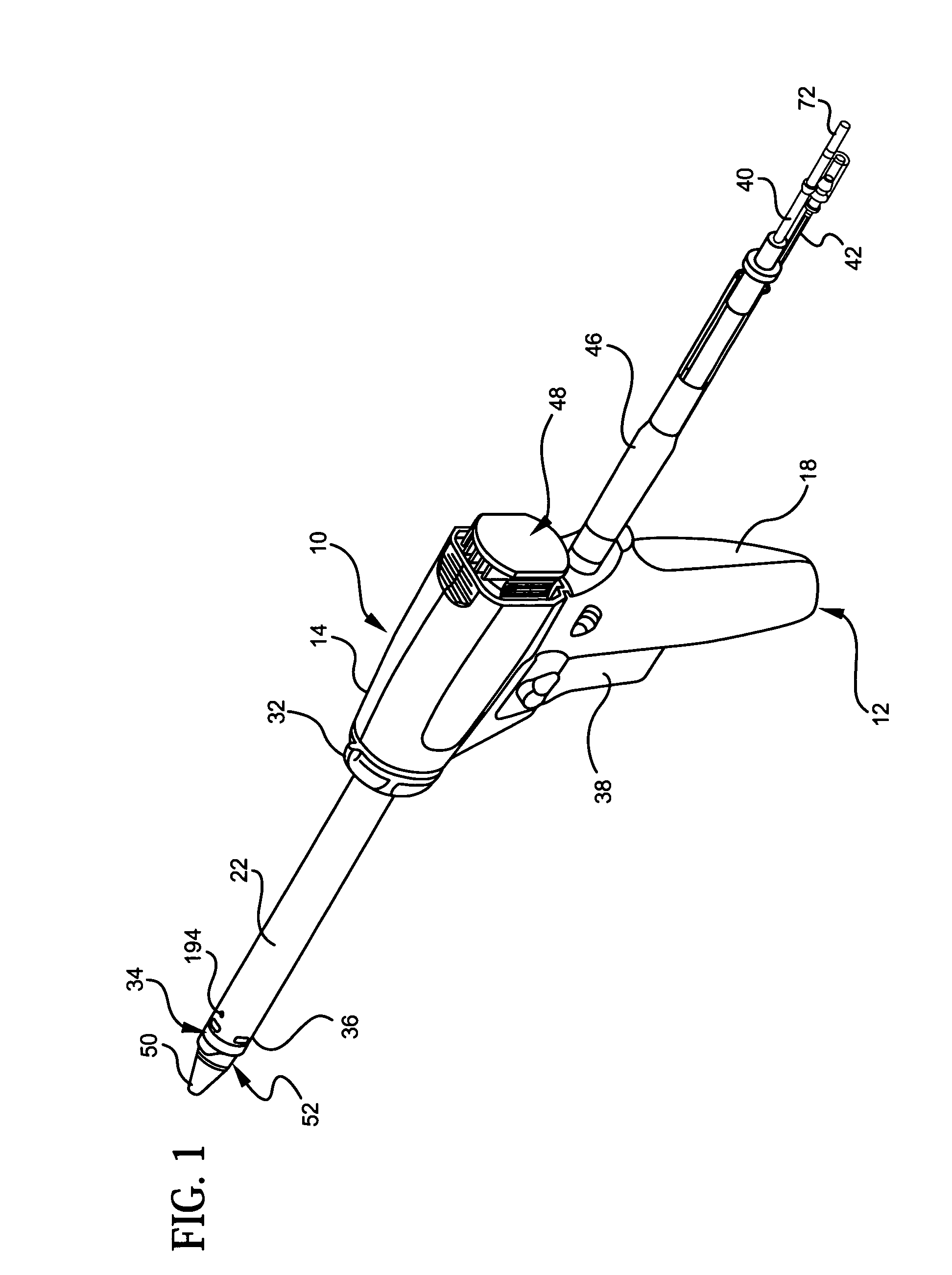
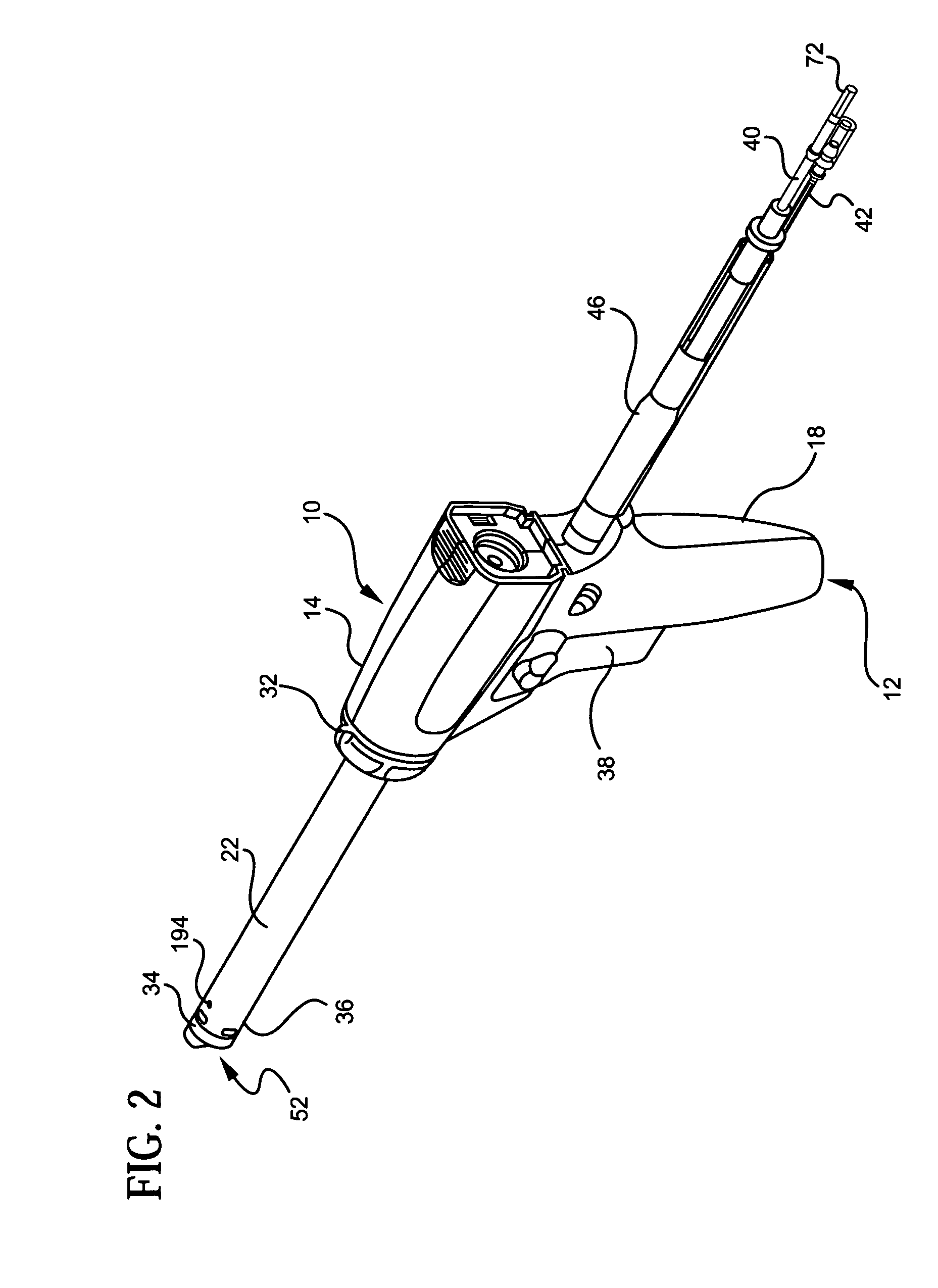
[0048]The present invention is directed to a surgical morcellator having a detachable handle. Currently, physicians use trocars for laparoscopic surgery, especially during gynecologic surgery. For situations where large tissue specimens or anatomical bodies, such as organs, require removal, a morcellator, such as described in the aforementioned Savage, et al. patent, is placed through the trocar to debulk the tissue, or the trocar is removed and the morcellator is placed through the existing incision into the patient's body.
[0049]Currently used morcellators are too bulky and heavy and have attached power leads or lines which make it difficult for the surgeon to accurately manipulate the morcellator during surgery. Also, currently used morcellators frequently require that the trocar be removed from the incision and the morcellator introduced therethrough, which prolongs surgery and creates additional trauma at the surgical site. Furthermore, because a trocar is limited in diameter, d...
PUM
 Abstract
Description
Claims
Application Information