Clamping and cutting apparatus for conveyor belts

a conveyor belt and cutting device technology, applied in the direction of metal working apparatus, metal-working machine components, manufacturing tools, etc., can solve the problems of operator taking too much time to turn, difficult to maintain a constant clamp force, unduly large torque applied by the operator to the drive handle, etc., to achieve a sufficiently high clamping force, rapid clamping operation, and the effect of generating sufficient clamping forces

Active Publication Date: 2012-03-13
FLEXIBLE STEEL LACING
View PDF10 Cites 7 Cited by
  • Summary
  • Abstract
  • Description
  • Claims
  • Application Information

AI Technical Summary

Benefits of technology

[0007]In another aspect, the upper and lower elongate members have at least one latching mechanism at an end thereof to allow for both easy and quick connection of the upper member to the lower member and removal therefrom. Preferably, the latching mechanism is provided at both ends of the elongate members. In addition, the latching mechanism preferably includes a latch pin carried by at least one link member of the end linkage assembly and which forms an outboard, anchored pivot connection in cooperation with a biased latch member operatively mounted to the lower elongate member.

Problems solved by technology

It has been found that this clamping arrangement on either side of the cutting blade requires that an operator apply an unduly large amount of torque on the drive handle for driving the cutting blade through the belt.
Further, since these clamping mechanisms employed compression springs, it has been found to be difficult to maintain a constant clamp force therewith as belt thicknesses vary.
Although other belt cutters have employed direct drive-type screw clamping mechanisms to better control the clamp force, these belt cutters required that an operator take too much time to turn the screw mechanisms to drive the clamp bar down into secure, clamping engagement with the conveyor belt to be cut, especially for relatively thin conveyor belts.

Method used


Image

  • Clamping and cutting apparatus for conveyor belts
  • Clamping and cutting apparatus for conveyor belts
  • Clamping and cutting apparatus for conveyor belts

Examples


Embodiment Construction

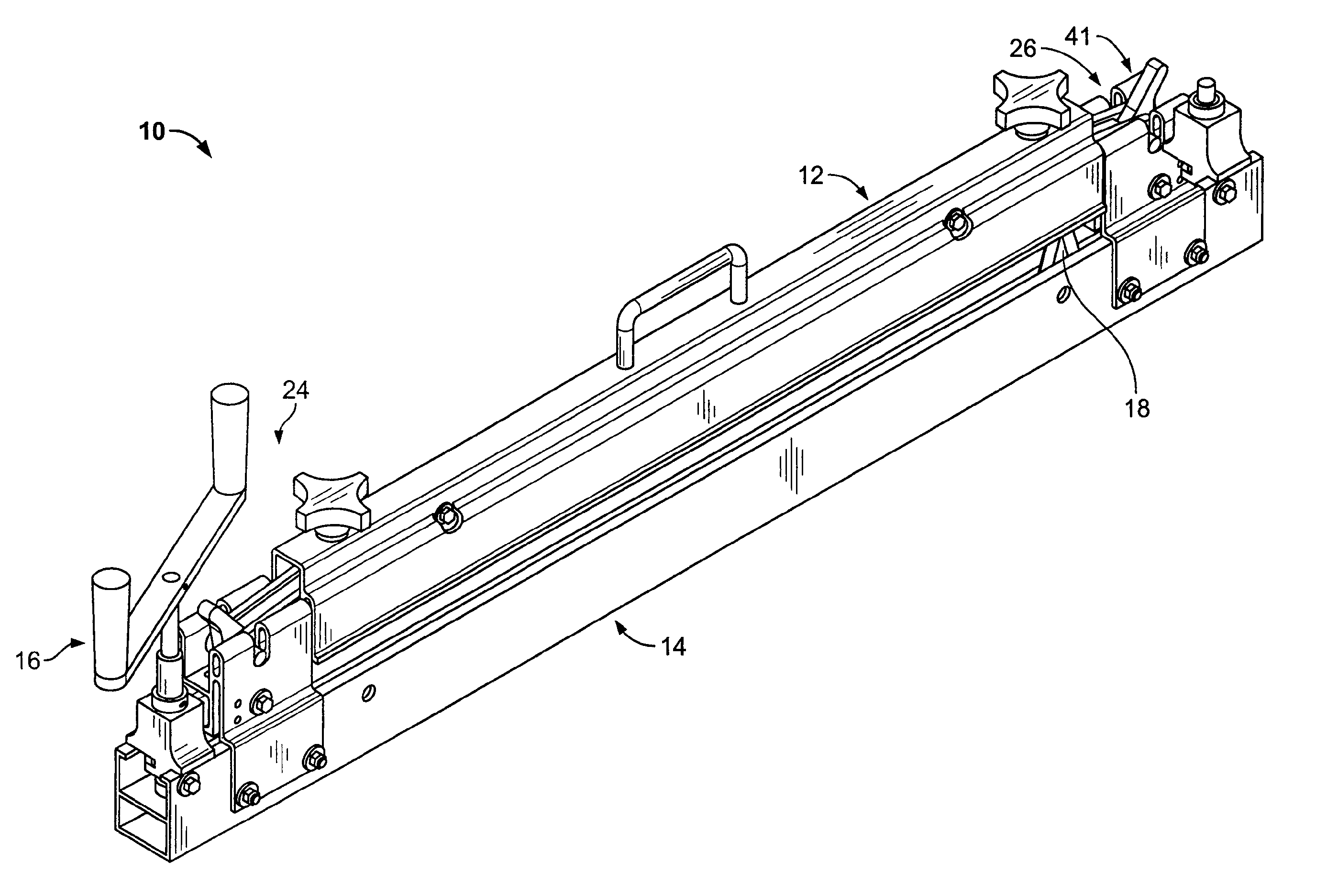
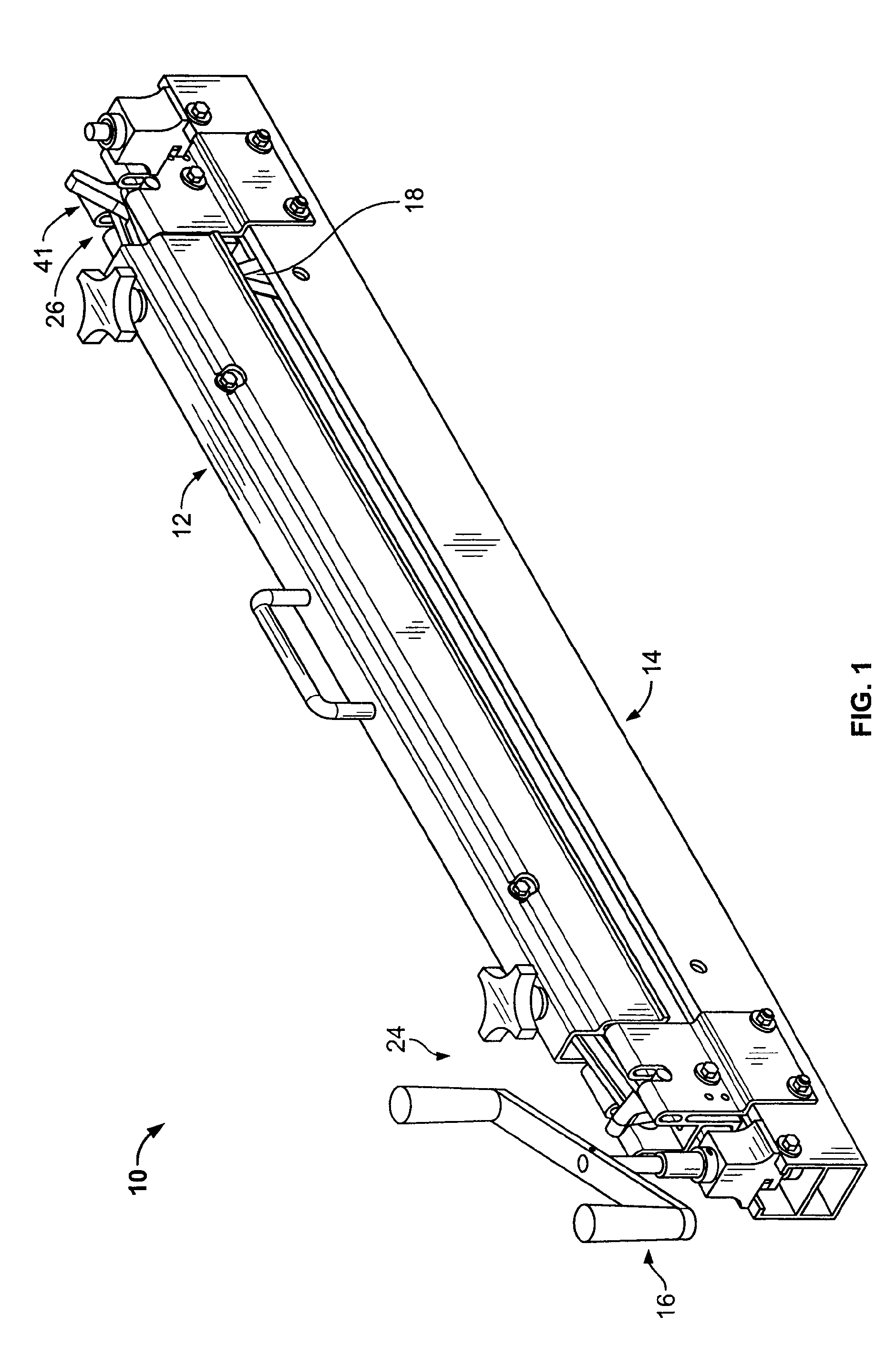
[0029]In FIG. 1, a belt clamping and cutting apparatus 10 that is operable to clamp a conveyor belt 23 and cut the conveyor belt across its width is shown. An alternative belt clamping and cutting apparatus 10′ (FIG. 22) is shown in FIGS. 22-31. The apparatus 10′ has its components all designated with primed reference numerals with similar components to those of apparatus 10 being designated with the same reference numeral except with a prime added thereto.

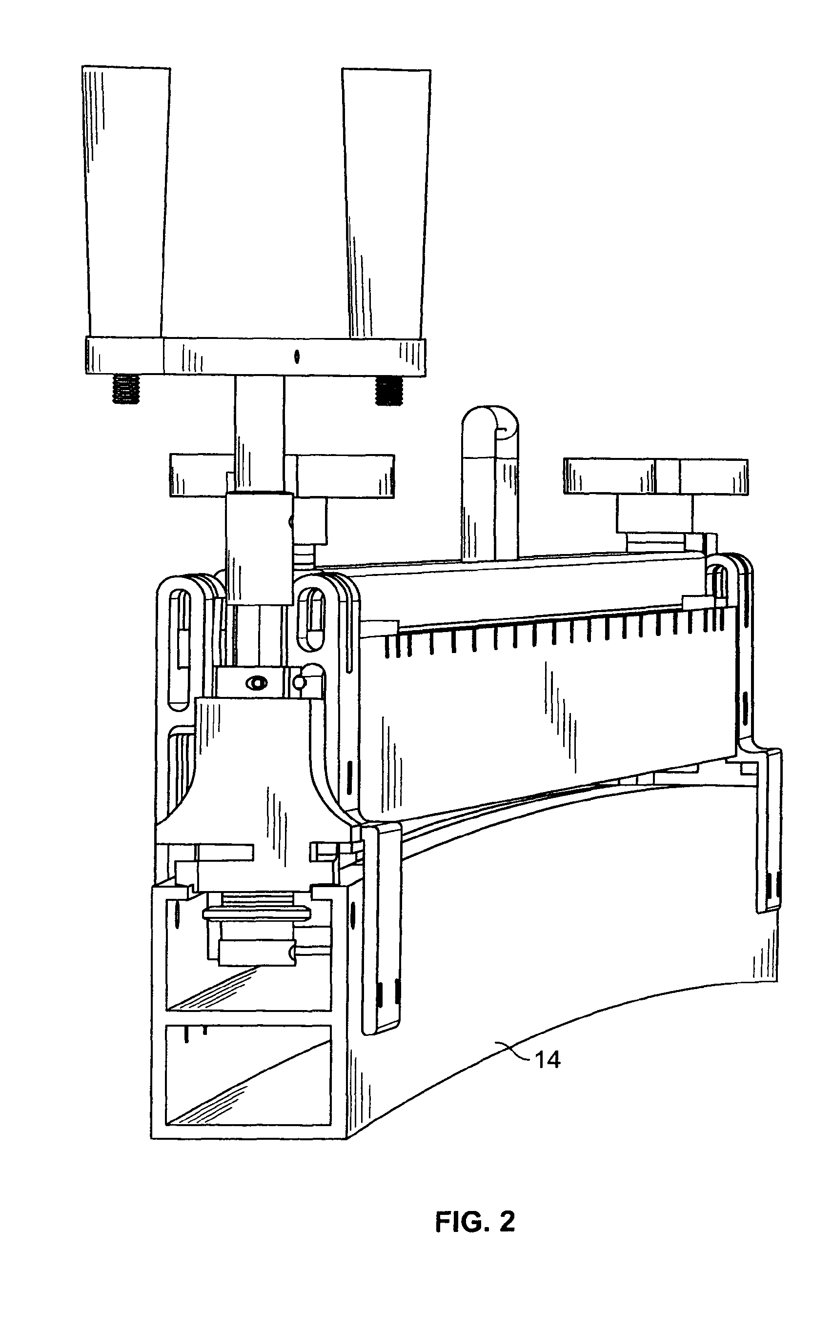
[0030]The belt cutting apparatus 10 has a long, upper clamp beam 12 (FIGS. 10-12) and an even longer, lower base member 14 (FIG. 21) between which the conveyor belt is clamped. The belt cutting apparatus 10 herein more efficiently transmits the torque applied to a drive handle 16 to a cutting blade 18 for driving the cutting blade 18 through the clamped conveyor belt so that the belt cutting apparatus 10 herein is much easier to operate than, for example, Applicant's assignee's prior belt cutter. In this regard, the upper clamp be...


PUM

PropertyMeasurementUnit
distanceaaaaaaaaaa
distanceaaaaaaaaaa
distanceaaaaaaaaaa

Abstract

A clamping and cutting apparatus for a conveyor belt is provided. The apparatus includes upper and lower elongate members between which the belt is to be clamped. A clamping mechanism has a screw drive mechanism mounted to the upper member and an end linkage assembly which are operable to generate a more rapid clamping operation of the elongate members on the belt. The upper elongate member can be releasably latched to the lower elongate member for quick connection and removal therefrom. A cutting blade of the apparatus is preferably provided with upper and lower guides to increase the rigidity thereof for increasing cutting accuracy and allowing thicker belts to be cut therewith without increasing blade thickness.

Description

FIELD OF THE INVENTION[0001]The invention relates to an apparatus for cutting conveyor belts, and more particularly, an apparatus that clamps across the width of a conveyor belt and cuts the conveyor belt therealong.BACKGROUND OF THE INVENTION[0002]For forming a belt splice, typically a conveyor belt is cut across its width at two locations to form squared ends of the belt that are then joined or spliced together with mechanical fasteners. Applicant's assignee herein has a belt cutter (the “840 Series Belt Cutter”) that has a long clamp bar with a pair of spring loaded, clamping mechanisms that clamp the conveyor belt between the clamp bar and a long base member. Thereafter, a cutting handle is operated to drive a cutting blade through the belt from one side of the belt to the other. In this belt cutter, the clamp bar has an inverted U-shaped configuration with opposite legs of the clamp bar clamping on the conveyor belt on either side of cutting blade. It has been found that this c...

Claims


Application Information

Patent Timeline
Patent Type & Authority Patents(United States)
IPC IPC(8): B26D7/02B25B1/20
CPCB26D7/02B26D1/04B26D5/08Y10T83/7507Y10T83/7527Y10T83/7553Y10T83/7567Y10T83/8822Y10T83/8847
Inventor ZIEGER, ANDREW J.
Owner FLEXIBLE STEEL LACING
Why Eureka
Try Eureka