Pressure gauge with pressure gauge assembly and connecting assembly

a technology of pressure gauge and connecting assembly, which is applied in the direction of fluid pressure measurement by electric/magnetic elements, measuring devices, instruments, etc., can solve the problem of not being able to twist between the pressure gauge assembly and the connecting assembly

Active Publication Date: 2012-12-11
WIKA ALEXANDER WIEGAND
View PDF10 Cites 1 Cited by
  • Summary
  • Abstract
  • Description
  • Claims
  • Application Information

AI Technical Summary

Benefits of technology

[0009]Also, the at least one annular passage portion can be circumferential. This arrangement permits the pressure gauge assembly to be rotated by 360° relative to the connecting assembly.
[0011]Furthermore, the pressure gauge assembly can be connected to the connecting assembly by way of a bayonet lock, the latter having a pre-detent and a setting area. This permits to easily and very quickly connect the pressure gauge assembly and the connecting assembly and to easily align the members with respect to one another.

Problems solved by technology

However, in said pressure gauges a twisting between the pressure gauge assembly and the connecting assembly is not possible due to the design.

Method used


Image

  • Pressure gauge with pressure gauge assembly and connecting assembly
  • Pressure gauge with pressure gauge assembly and connecting assembly
  • Pressure gauge with pressure gauge assembly and connecting assembly

Examples


Embodiment Construction

[0019]The invention will now be described with reference to the drawing figures, in which like reference numerals refer to like parts throughout.

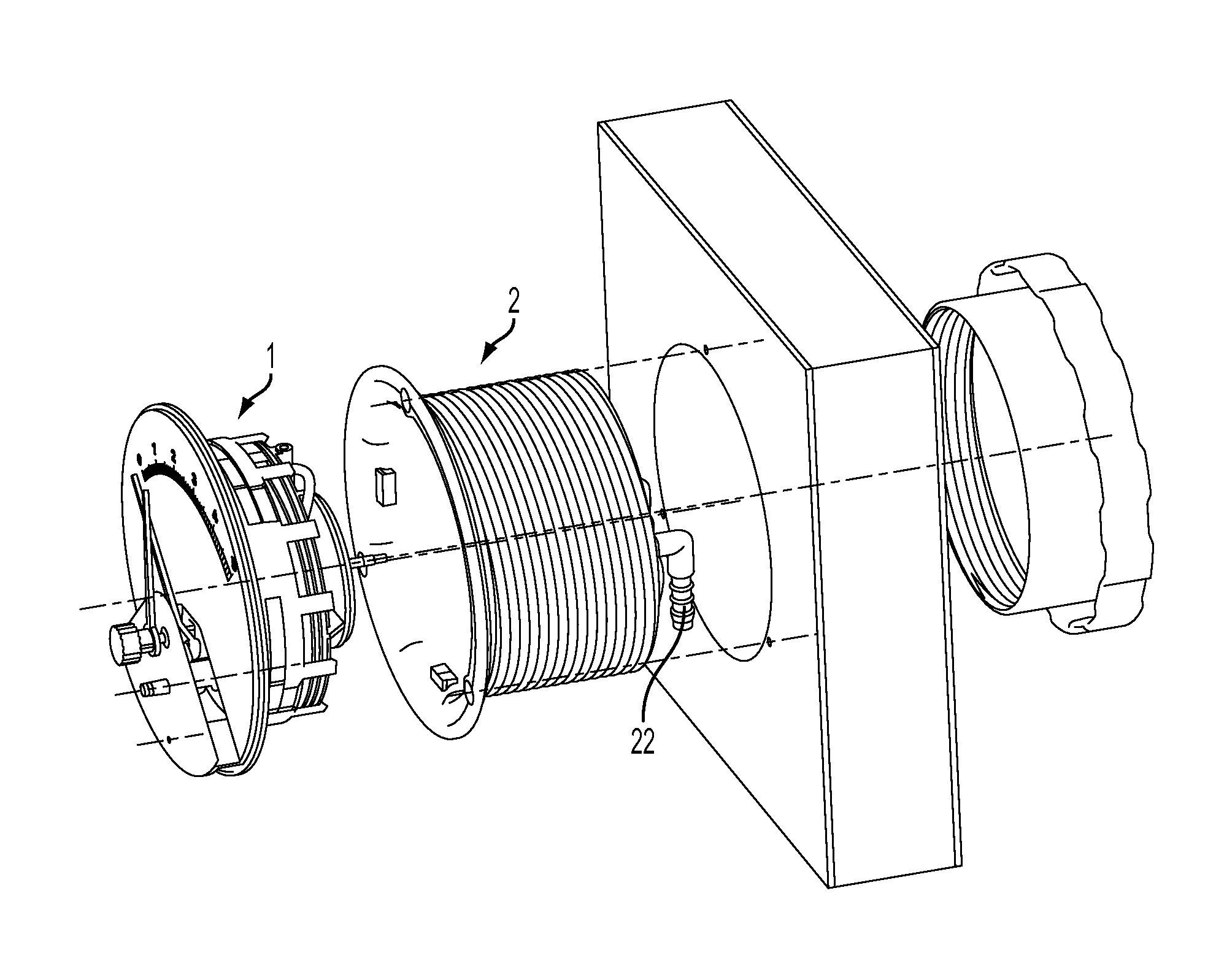
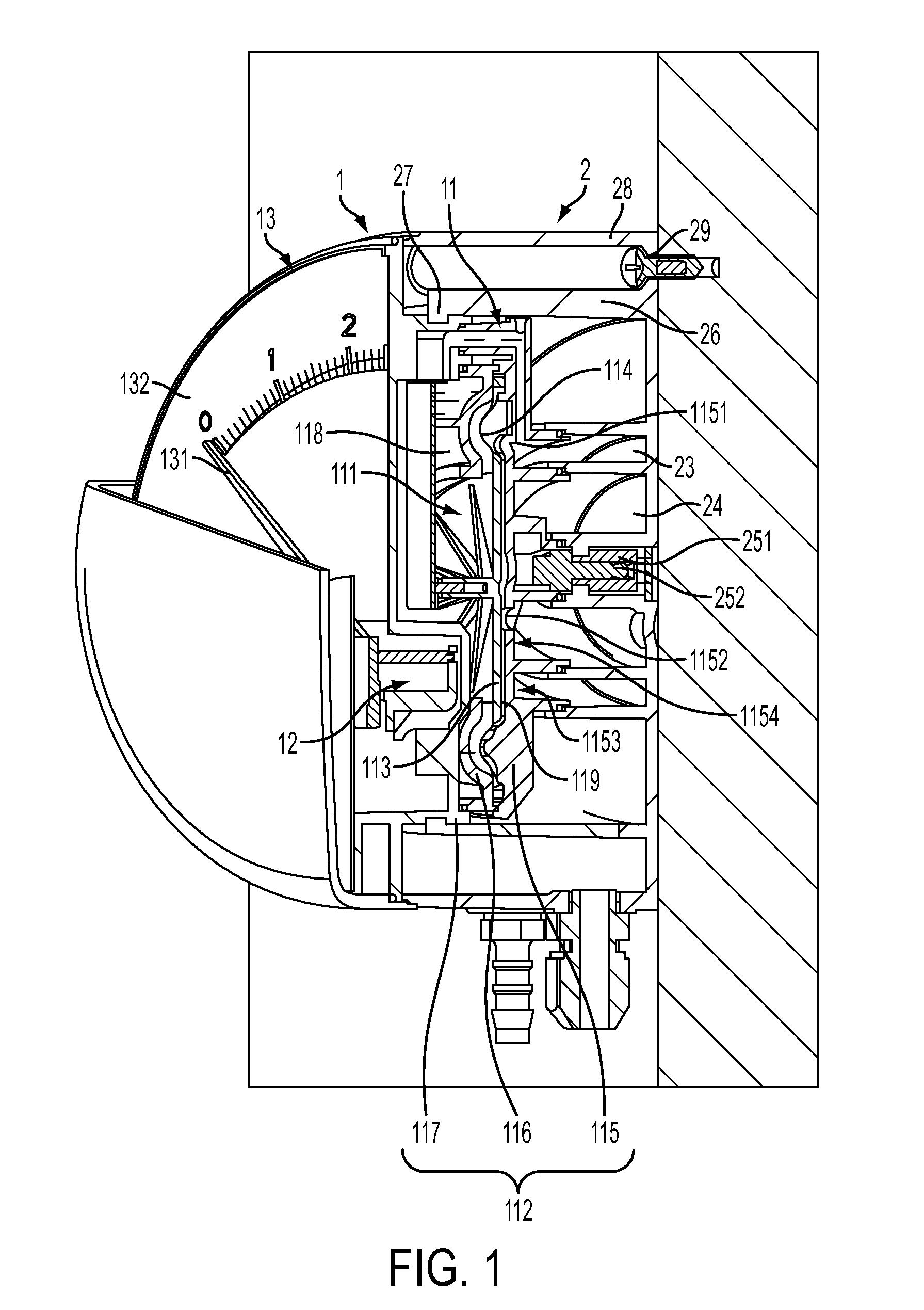
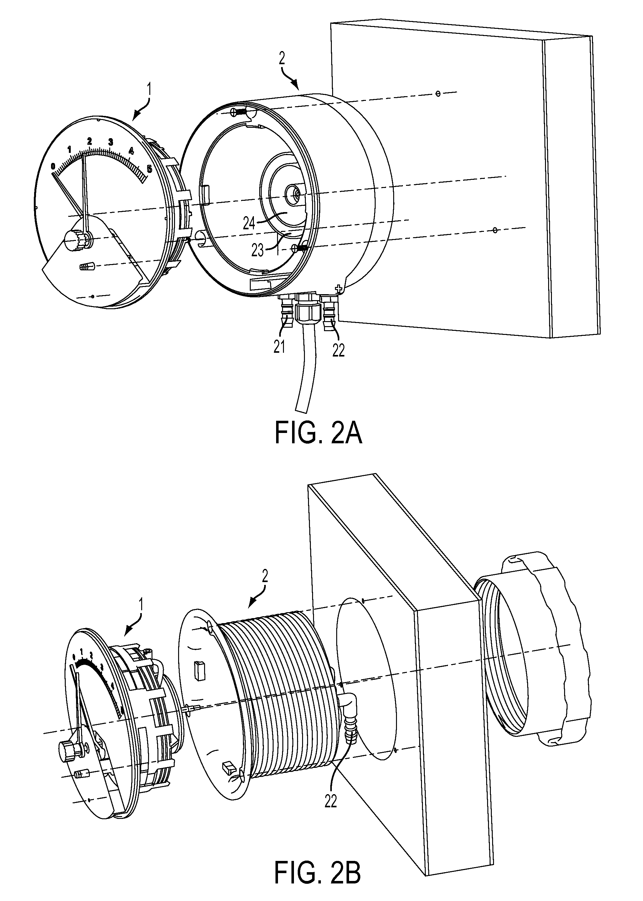
[0020]In the embodiment the pressure gauge is realized as differential pressure gauge. FIG. 1 illustrates the structure of the pressure gauge. The pressure gauge assembly 1 mainly consists of a mechanical metering element 11 to which a meter movement 12 and a display 13 are operatively connected. Moreover, the mechanical metering element 11 includes a sensor, not shown, for electrically picking off a movement of the metering element 11.

[0021]The metering element 11 in the current case consists of a membrane 111 and a membrane support 112.

[0022]The membrane 111 has a two-part structure including a disk-shaped central portion 113 and an edge portion 114 connected to the central portion 113 and completely enclosing the edge thereof. In the current case, the central portion 113 is circular. It may also have other shapes, however.

[0023]The centr...


PUM

PropertyMeasurementUnit
pressureaaaaaaaaaa
circumferential shapeaaaaaaaaaa
areaaaaaaaaaaa

Abstract

A pressure gauge comprises a pressure gauge assembly and a connecting assembly. The pressure gauge assembly includes a measuring pressure port for the pressure to be measured and the connecting assembly includes a pressure measuring port. The pressure gauge assembly is adapted to be connected to the connecting assembly. In order to permit a relative rotation between the pressure gauge assembly and the connecting assembly, the pressure gauge assembly and / or the connecting assembly supports at least one annular passage section connecting the measuring pressure port to the pressure measuring port.

Description

CROSS-REFERENCE TO RELATED APPLICATIONS[0001]This application claims priority to German Patent Application 10 2008 002 312.4, filed on Jun. 9, 2008, the disclosure of which is incorporated herein by reference in its entirety.FIELD OF THE INVENTION[0002]The invention relates to a pressure gauge comprising a pressure gauge assembly and a connecting assembly, wherein, in the assembled state, a rotation of the pressure gauge assembly relative to the connecting assembly is possible.BACKGROUND OF THE INVENTION[0003]Pressure gauges are known which comprise a pressure gauge assembly and a connecting assembly. In this type of pressure gauges, the pressure gauge assembly and the connecting assembly are fixedly connected to each other and the connecting assembly is connected to an object at which a pressure is to be measured. However, in said pressure gauges a twisting between the pressure gauge assembly and the connecting assembly is not possible due to the design.SUMMARY OF THE INVENTION[000...

Claims


Application Information

Patent Timeline
Patent Type & Authority Patents(United States)
IPC IPC(8): G01L9/00
CPCG01L19/003G01L7/082
Inventor BARMETTLER, PETERARNOLD, ANDREASDISLER, ALEXKOLB, ANDREAS
Owner WIKA ALEXANDER WIEGAND
Why Eureka
Try Eureka