Soil probing device having threaded male and female bayonet columns

a probing device and bayonet column technology, applied in the field of soil probing devices, can solve the problems of time-consuming and labor-intensive screwing time-consuming and labor-intensive unscrewing of the rod sections, etc., and achieve the effect of quick and easy connection to one, easy and fast operation, and easy sliding into each other

Inactive Publication Date: 2016-10-20
A H VAN DEN BERG HLDG
View PDF7 Cites 8 Cited by
  • Summary
  • Abstract
  • Description
  • Claims
  • Application Information

AI Technical Summary

Benefits of technology

[0011]This advantageously makes it possible for the rod sections to be quickly and easily connected to one another. The alternating threaded columns and spacings of the male and female locking parts can easily be slid into each other in the axial direction, after which the plurality of complementary male and female screw thread turn sections can all at the same time be engaged into each other by means of merely a limited rotation of less than a full turn, in particular even less than 90 degrees. Thus the invention combines the strength of a screw thread connection that has been screwed over a plurality of turns into each other, with the ease of a bayonet-type of insert / rotate connection movement. It has appeared that the thus obtained connections between the rod sections are more than strong enough for the aimed penetration of the probing rod into the ground. The connection process of a new rod section to the probing rod can be performed such easy and quickly that it does not have to negatively influence any penetration measurements that are performed at the same time. The connection process requires little space upstream of the drive means, and thus makes the building of a compact device possible.
[0020]In a variant at least three of the threaded male bayonet columns and at least three of the threaded female bayonet columns are provided that are equally distributed over the circumference of their respective male and female locking parts. Thus a symmetrical engagement of the columns into each other is possible, which helps to equally distribute the pulling forces over the locking parts and also helps to keep the rotating towards the axially aligned position and / or towards the locked position limited to less than 60 degrees.

Problems solved by technology

A disadvantage with this known device is that the screwing of the rod sections together is time-consuming.
Also this screwing of the rod sections is difficult to automate, particularly when it is desired to perform the screwing of a new rod section to the probing rod at the same time that this probing rod is forced to penetrate at a constant speed into the ground in one continuous go.
Another disadvantage is that during a removing of the probing rod out of the ground again, the unscrewing of the rod sections also is time-consuming and difficult to automate.
Furthermore it then sometimes appears that the screw connections have gotten screwed together too tight and can only be loosened with great difficulty.
A disadvantage with this is that the preassembling of the probing rod on the ship is time-consuming and makes the operational costs for the ship expensive.
Furthermore the preassembling process of the probing rod is sensitive for weather conditions and swells.
Also the assembly of the preassembled probing rod and support mast is vulnerable because of its great length, not only during the preassembly process itself but also during its lowering towards the sea floor, which can be more than 2000 metres below.
Further it is disadvantageous that a heavy winch is needed for lowering the assembly to the sea floor, while at the same time means need to be provided for keeping the support mast and the preassembled probing rod in an upright position.
A disadvantage with this however is that the probing rod during its unwinding of the large diameter storage wheel needs to be plastically deformed such that it gets straight.
This makes this type of soil probing device costly.
Another disadvantage is that the required plastic deformation makes it necessary to use a relative slender elongate probing rod, because otherwise the plastic deformation would become too difficult.
However such a relative slender probing rod has limited strength and limits the maximum penetration depth.
Also it entails the risk that it may start to plastically deform and deviate from its aimed vertical penetration path when running against obstacles.

Method used


Image

  • Soil probing device having threaded male and female bayonet columns
  • Soil probing device having threaded male and female bayonet columns
  • Soil probing device having threaded male and female bayonet columns

Examples


Embodiment Construction

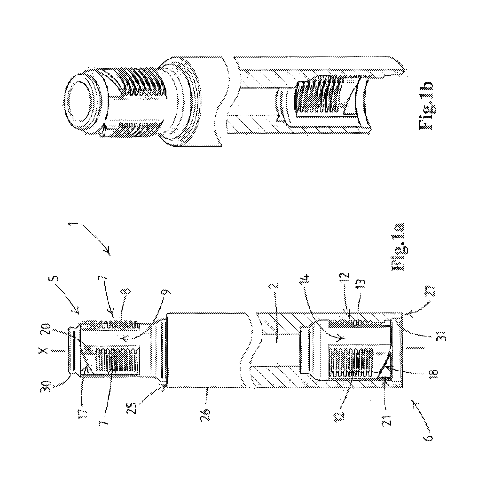
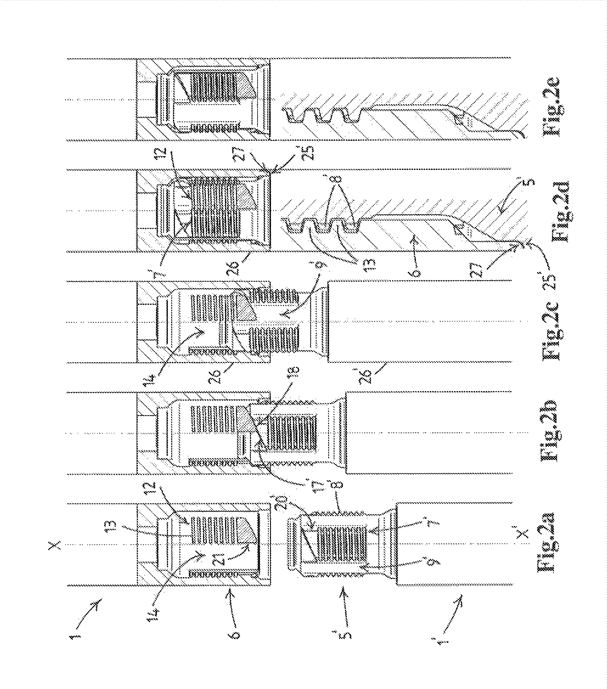
[0032]In FIG. 1 a rod section for a probing rod is indicated in its entirety with the reference numeral 1. The rod section 1 is formed by a straight hollow tube that delimits a hollow channel 2 with a central axis that extends in an axial direction x. The rod section 1 comprises a male locking part 5 at its upper free end and a complementary female locking part 6 at its lower free end. With this the hollow channel 2 extends through the entire rod including through both the locking parts 5, 6.

[0033]The male locking part 5 has a reduced outer diameter relative to the rest of the rod section 1 and comprises three spaced apart threaded male bayonet columns 7 that are equally divided around its circumference. Each column 7 comprises an array of a plurality of right-handed screw thread turn sections 8 that lie above one another in the axial direction x. Slit-shaped smooth spacings 9 lie in between the columns 7.

[0034]The female locking part 6 has an increased inner diameter relative to th...


PUM

PropertyMeasurementUnit
rotation angleaaaaaaaaaa
lengthsaaaaaaaaaa

Abstract

A soil probing device for determining properties of soil during penetration into ground. Soil probing device has a measuring probe, a plurality of rod sections each having a central axis for assembly of the probing rod, driving means for penetrating the probing rod into the ground, and a measuring means for determining properties of the ground during penetration of the probing rod into the ground. Each of the rod sections is provided at outer ends with complementary male and female locking parts moveable relative to each other from an unlocked to a locked position. The male locking part has two or more threaded male bayonet columns, each male bayonet column having a plurality of radially outwardly projection screw thread turn sections. The female locking part has two or more threaded female bayonet columns, each threaded female bayonet column having a plurality of radially inwardly projecting screw thread turn sections.

Description

CROSS-REFERENCE TO RELATED APPLICATIONS[0001]This application claims the benefit of Netherlands Application No. NL 2014658, filed Apr. 17, 2015, the contents of which is incorporated by reference herein.FIELD OF THE INVENTION[0002]The present invention relates to the field of soil probing devices for determining geophysical and geotechnical properties of soil during penetration of a probing rod into the ground at land or at sea floors.BACKGROUND OF THE INVENTION[0003]Soil probing devices are known in various embodiments. For example EP 0 989 240, that was filed in the name of the present applicant, shows a soil probing device that has two sets of clamping members that can be moved up and down independently from each other and that are designed to alternately clamp a probing rod and push it gradually into the ground. Cone penetration measurements are performed during this penetration for determining the desired geophysical and geotechnical properties of the soil. The soil probing dev...

Claims


Application Information

Patent Timeline
Patent Type & Authority Applications(United States)
IPC IPC(8): G01N3/42G01N33/24
CPCG01N33/24G01N3/42E02D1/022F16L37/2445
Inventor HOEKSTRA, AREND TJEERD
Owner A H VAN DEN BERG HLDG
Why Eureka
Try Eureka