Clipping device

a technology of clipping device and clip, which is applied in the field of clipping device, can solve the problems of cumbersome latching, cumbersome mounting operation of the clip unit, and small size of the clip unit itsel

Active Publication Date: 2012-05-08
OLYMPUS CORP
View PDF24 Cites 157 Cited by
  • Summary
  • Abstract
  • Description
  • Claims
  • Application Information

AI Technical Summary

Benefits of technology

[0011]A further object of the present invention is to provide a clipping device which prevents a drop of a coupling member for latching a clip.
[0012]Another object of the present invention is to provide a clipping device which ensures a better insertability into an endoscope.
[0013]A further object of the present invention is to provide a clipping device which can be easily used under in combination with a side viewing or oblique viewing scope.

Problems solved by technology

The clip unit itself was very small in size and it was cumbersome to latch a coupling plate of the clip unit to the hook member fixed to the distal end of the operation wire.
The mounting operation of the clip unit was cumbersome and it took a lot of time to prepare the clipping device for actual use.
However, the coupling member itself was very small, thus making it difficult to find.
In addition, the removal operation was also cumbersome.
These operations took a long time to perform, thus placing a greater burden was placed on the patient.
If the hook member is so drawn deep into the coil sheath, then it takes a long time to mount a new clip unit on the rest of the device.
For this reason, the length of the rigid section area near that distal end is made longer by the amount of the rigid member and the insertion operation into the endoscope becomes more cumbersome with a resultant disadvantage.
If, therefore, the length of the rigid section area near the distal end section is made greater, the insertion operation into the endoscope becomes much more cumbersome.
Further, where the clipping device is used in combination with the side viewing and oblique viewing scopes, the coil sheath into which the hook member is drawn is tightly bent, so that the hook member is liable to be deformed when it is drawn into the coil sheath.
When the hook member is so deformed, then it becomes difficult to mount a new clip on the device body.
It has, therefore, been considered difficult to use the clipping device in combination with side viewing and oblique viewing scopes.
Further, the coupling method of the clip and device body poses a problem such as the dropping of the clip out of the device body due to vibration or drop page during a transport, etc.

Method used


Image

  • Clipping device
  • Clipping device
  • Clipping device

Examples


first embodiment

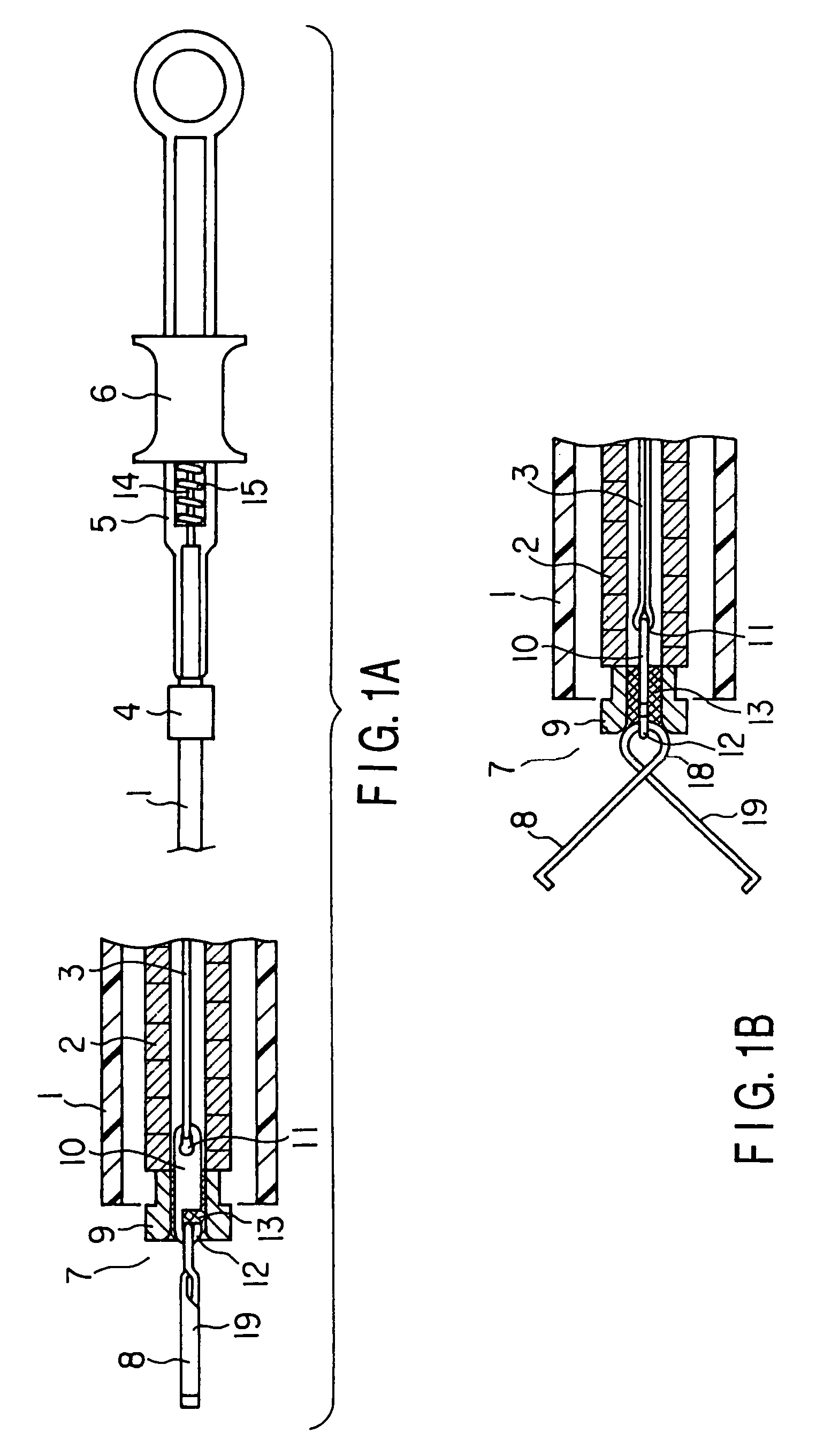
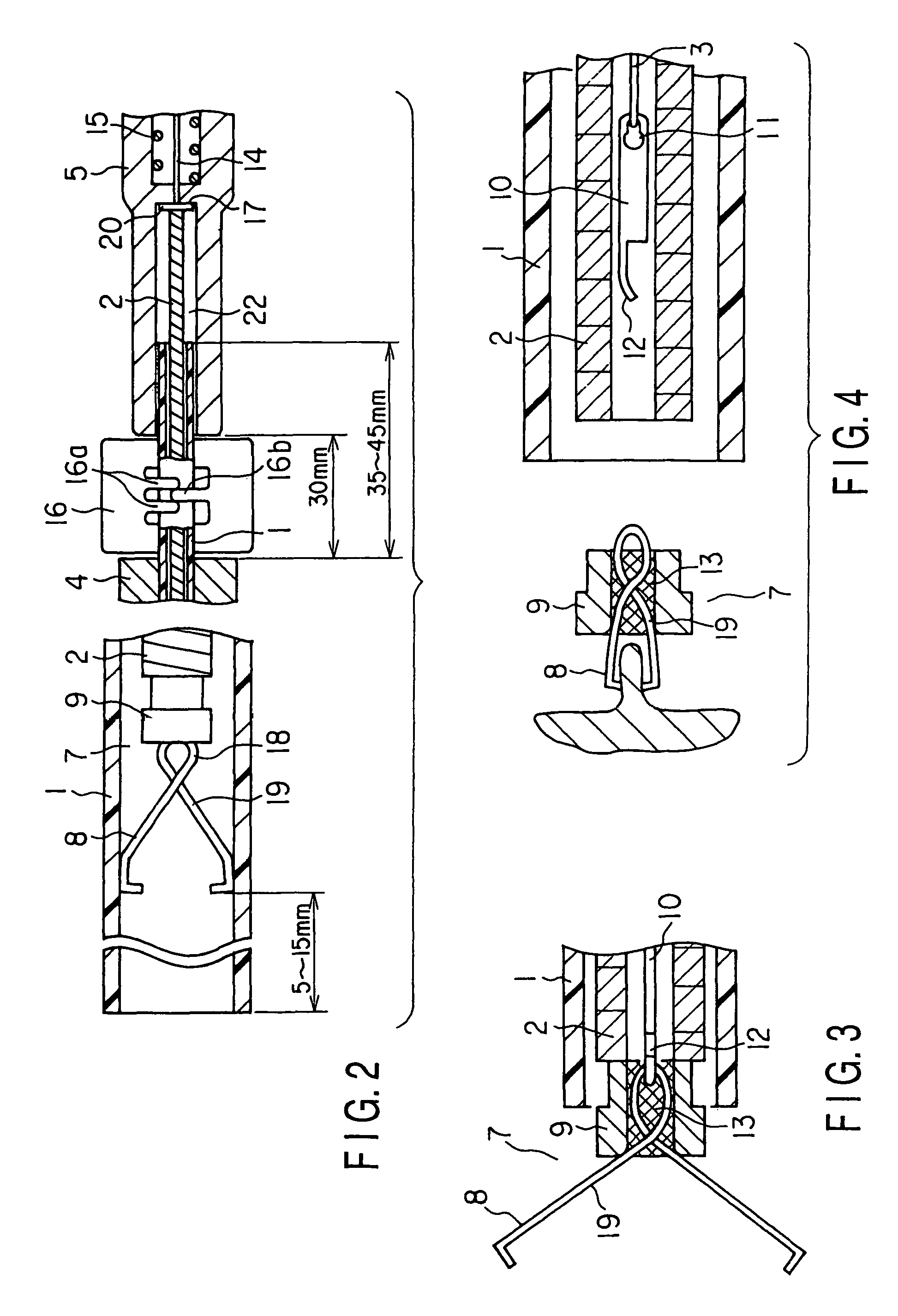
[0039]A clipping device according to the present invention which is used for an endoscope will be described below with reference to FIGS. 1 to 6.

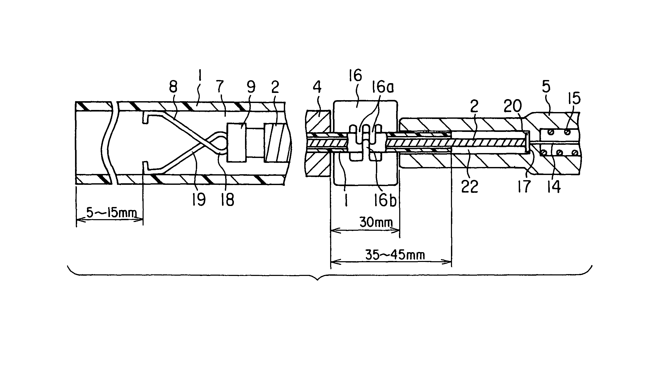
[0040]As shown in FIG. 1A, the clipping device according to the embodiment which is used for the endoscope is constructed such that its member introduced into a body cavity of a subject comprises an insertion tube 1 comprised of a high density polyethylene tube, etc., and has an inner / outer diameter size of about φ2.1 mm / 2.5 mm and a coil sheath 2 serving as a sheath member, inserted into the insertion tube 1 in a way to be movable back and forth. Into the coil sheath 2 an operation wire 3 made of, for example, stainless steel is inserted in a way to be movable back and forth and is covered with high density polyethylene. An operation section is provided near a base end of the insertion tube 1 fitted over an outer periphery of the coil sheath 2. The operation section comprises a silicone grip (first operation means) 4 so mounted as to be pr...

second embodiment

[0063]A clipping device according to the present invention for use in an endoscope will be explained below by referring to FIG. 7.

[0064]This embodiment is different from the first embodiment in that a hole formed at a proximal side end of a coupling member 10 is used as a hook 21. The remaining structure is the same as that of the first embodiment. The hook 21 is adequately higher in elongation strength than a distal end side hook section 12 of the coupling plate 10. Further, the width of an opening 21a of the hook 21 is made somewhat narrower than a diameter of the operation wire 3.

[0065]This embodiment is different from the first embodiment in that a clip 8 is detachable. After the clipping of an initially attached clip 8, a slider 6 is pushed until it abuts against a forward end. By doing so, doubled-back portions of the operation wire 3 are projected from the distal end of a coil sheath 2 and the coupling plate 10 is detached from the operation wire 3 by utilizing the elasticity...

third embodiment

[0067]A clipping device for use in an endoscope will be explained below by referring to FIGS. 8 to 15.

[0068]This embodiment is different from the first embodiment in terms of a coupling plate 10, operation wire 3, operation section body 5, slider 6 and clip unit 7 only. The other structure is the same as that of the first embodiment set out above.

[0069]In this embodiment, as shown in FIG. 8A, a substantially tube-like fixing section 54 having a slit 53 is provided at a proximal side end portion of the coupling plate 10 and, as shown in FIG. 8B, the distal end portion of the operation wire 3 is passed through the tube-like fixing section 54 and, by the press-fitting of the fixing section 54, the distal end portion of the operation wire 3 is fixed to the fixing section 54.

[0070]The fixing of the operation wire 3 and fixing section 54 may be done by means of laser welding, brazing, etc. It is desirable to set the length of the fixing section 54 to below 30 mm from the standpoint of a ...


PUM


Abstract

The present invention provides a clipping device having a coil sheath inserted into an insertion tube in a back / forth movable way to allow it to be inserted into a body cavity, an operation wire inserted into the coil sheath in a back / forth movable way, and a clip directly connected to a distal end of the operation wire to allow it to clip a living tissue.

Description

CROSS-REFERENCE TO RELATED APPLICATION[0001]This application is a continuation application of U.S. Ser. No. 10 / 072,721 filed Feb. 6, 2002, which is based upon and claims the benefit of priority from the prior Japanese Patent Application No. 2001-029839, filed Feb. 6, 2001 the entire contents of each of which are incorporated herein by reference.BACKGROUND OF THE INVENTION[0002]The present invention relates to a clipping device for performing an operation, such as stopping bleeding, in living tissue with the use of a clip.[0003]The clipping device disclosed in Jpn. Pat. Appln. KOKAI Publication No. 8-280701 has an operation tube slidably located into an insertion tube and a coupling ring fixedly mounted on the distal end of the operation tube to hold a clip unit in place. In this publication, a hook member is connected to the distal end of an operation wire inserted into the operation tube and the clip unit is detachably latched to the hook member. Since, in this clipping device, the...

Claims


Application Information

Patent Timeline
Patent Type & Authority Patents(United States)
IPC IPC(8): A61B17/10A61B17/08A61D1/00A61B17/064A61B17/12A61B17/122A61B17/128A61B17/28
CPCA61B17/122A61B17/1285A61B17/0643A61B2017/2905
Inventor MATSUNO, KIYOTAKAKIMURA, KOH
Owner OLYMPUS CORP
Why Eureka
Try Eureka