Thermal energy storage and cooling system utilizing multiple refrigerant and cooling loops with a common evaporator coil

a technology of energy storage and cooling system, which is applied in the direction of cooling fluid circulation, domestic cooling apparatus, lighting and heating apparatus, etc., can solve the problems of difficulty in achieving high-efficiency and limited success of current air conditioning units having energy storage systems, and achieve the effects of facilitating thermal contact, reducing the enthalpy of the second refrigerant, and facilitating heat transfer

Inactive Publication Date: 2012-05-22
GREENER ICE SPV L L C
View PDF103 Cites 19 Cited by
  • Summary
  • Abstract
  • Description
  • Claims
  • Application Information

AI Technical Summary

Benefits of technology

[0004]An embodiment of the present invention may therefore comprise a refrigerant-based thermal energy storage and cooling system comprising: a first refrigerant loop containing a first refrigerant comprising: a first condensing unit, the first condensing unit comprising a first compressor and a first condenser; a first expansion device connected downstream of the first condensing unit; and, a primary heat exchanger connected between the first expansion device and the first condensing unit that acts as an evaporator and is located within a tank filled with a fluid capable of a phase change between liquid and solid, the primary heat exchanger that facilitates heat transfer from the first refrigerant from the first condenser to cool the fluid and to freeze at least a portion of the fluid within the tank; a second refrigerant loop containing a second refrigerant comprising: a second condensing unit, the second condensing unit comprising a second compressor and a second condenser; a second expansion device connected downstream of the second condensing unit; and, a load heat exchanger connected between the second expansion device and the second condensing unit; an isolating heat exchanger that facilitates thermal contact between the cooled fluid and the second refrigerant thereby reducing the enthalpy of the second refrigerant and that returns warmed fluid to the tank.
[0005]An embodiment of the present invention may also comprise a refrigerant-based thermal energy storage and cooling system comprising: a first refrigerant loop containing a first refrigerant comprising: a first condensing unit, the first condensing unit comprising a first compressor and a first condenser; a first expansion device connected downstream of the first condensing unit; and, a primary heat exchanger connected between the first expansion device and the first condensing unit that acts as an evaporator and is located within a tank filled with a fluid capable of a phase change between liquid and solid, the primary heat exchanger that facilitates heat transfer from the first refrigerant from the first condenser to cool the fluid and to freeze at least a portion of the fluid within the tank; a second refrigerant loop containing a second refrigerant comprising: a second condensing unit, the second condensing unit comprising a second compressor and a second condenser; a second expansion device connected downstream of the second condensing unit; and, a load heat exchanger connected between the second expansion device and the second condensing unit; a cooling loop containing a heat transfer material comprising: an isolating heat exchanger that facilitates thermal contact between the cooled fluid and the heat transfer material and that returns warmed fluid to the tank; and, a sub-cooling heat exchanger that facilitates thermal contact between the heat transfer material and the second refrigerant thereby reducing the enthalpy of the second refrigerant and that returns warmed heat transfer material to the isolating heat exchanger.
[0009]An embodiment of the present invention may also comprise a method of providing cooling with a thermal energy storage and cooling system comprising the steps of: compressing and condensing a first refrigerant with a first air conditioner unit to create a first high-pressure refrigerant; expanding the first high-pressure refrigerant; providing cooling to a primary heat exchanger with the first refrigerant in the primary heat exchanger that is constrained within a tank containing a fluid capable of a phase change between liquid and solid; freezing a portion of the fluid and forming ice and cooled fluid within the tank during a first time period; compressing and condensing a second refrigerant with a second air conditioner unit to create a second high-pressure refrigerant; and, expanding the second high-pressure refrigerant in a load heat exchanger to provide load cooling during a second time period; transferring cooling from the cooled fluid to a heat transfer material in a cooling loop; transferring cooling from the heat transfer material to the second refrigerant after the second refrigerant leaves the second air conditioner thereby reducing the enthalpy of the second refrigerant; and expanding the second high-pressure refrigerant in the load heat exchanger to provide load cooling during a third time period.

Problems solved by technology

Current air conditioning units having energy storage systems have had limited success due to several deficiencies, including reliance on water chillers that are practical only in large commercial buildings and have difficulty achieving high-efficiency.

Method used


Image

  • Thermal energy storage and cooling system utilizing multiple refrigerant and cooling loops with a common evaporator coil
  • Thermal energy storage and cooling system utilizing multiple refrigerant and cooling loops with a common evaporator coil
  • Thermal energy storage and cooling system utilizing multiple refrigerant and cooling loops with a common evaporator coil

Examples


Embodiment Construction

[0019]While this invention is susceptible to embodiment in many different forms, it is shown in the drawings, and will be described herein in detail, specific embodiments thereof with the understanding that the present disclosure is to be considered as an exemplification of the principles of the invention and is not to be limited to the specific embodiments described.

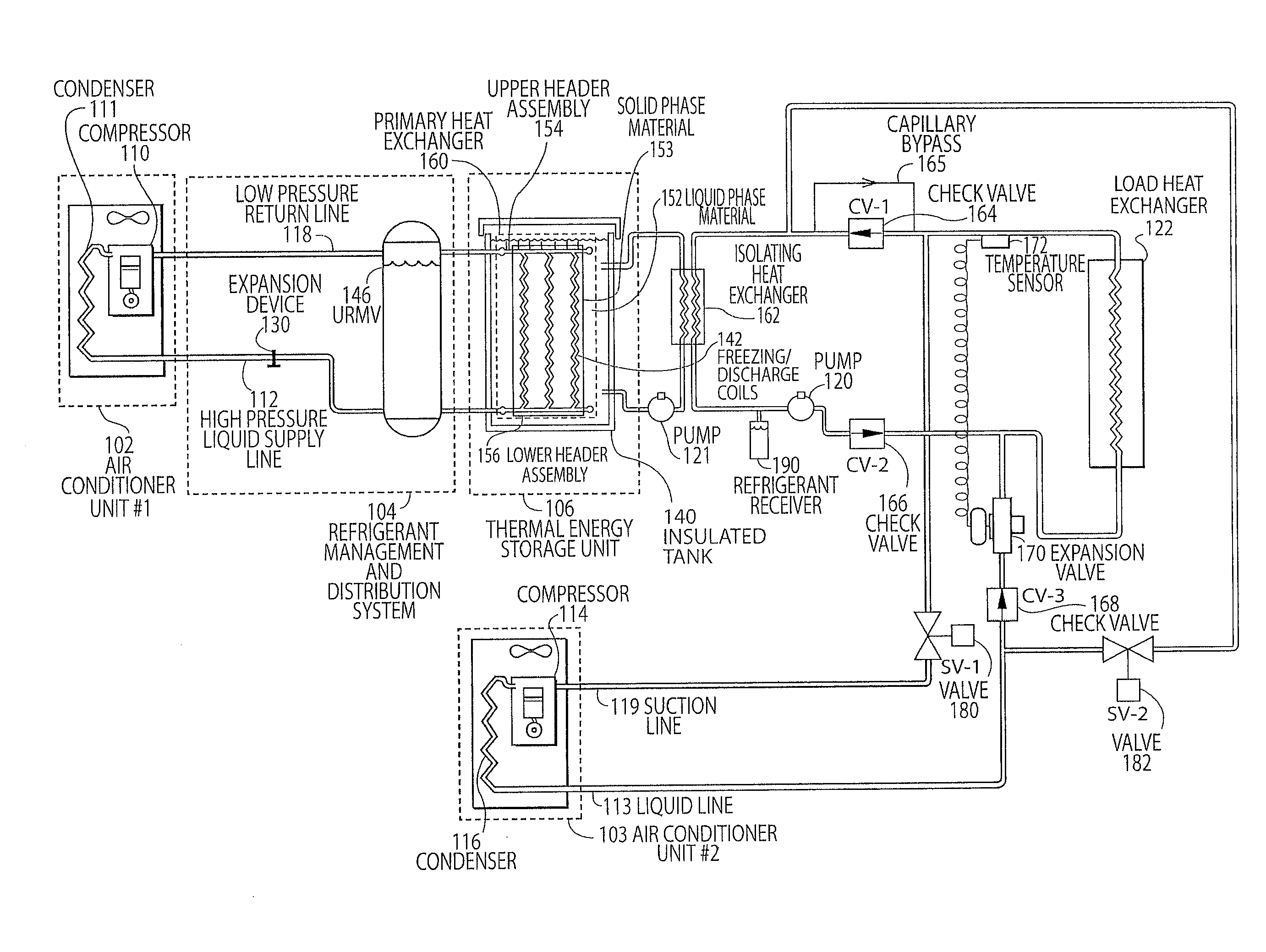
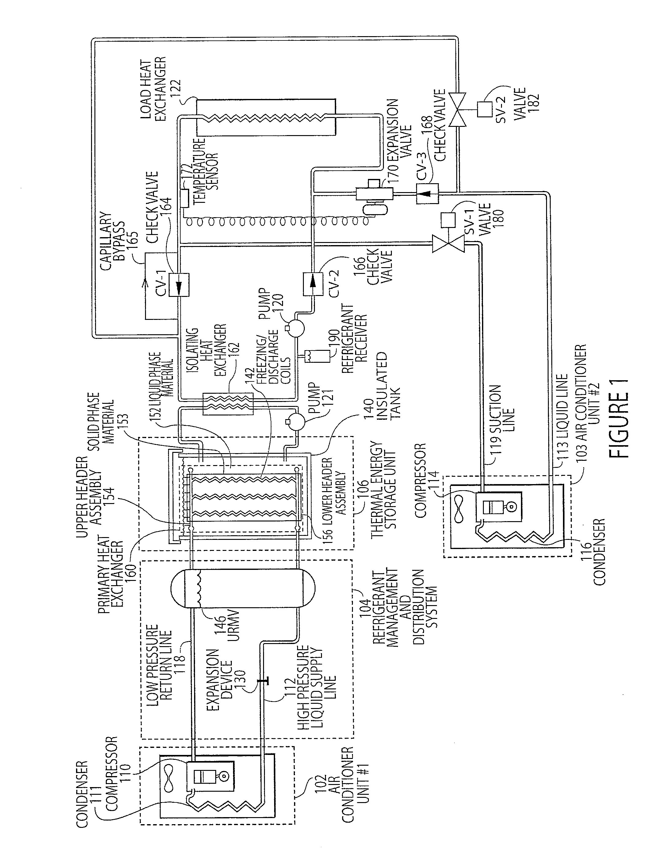
[0020]FIG. 1 illustrates an embodiment of a thermal energy storage and cooling system with multiple condensing units utilizing a common evaporator coil. This embodiment may function with or without an accumulator vessel or URMV 146 (universal refrigerant management vessel), and is depicted in FIG. 1 with the vessel in place in the primary refrigerant loop with the first air conditioner unit #1102 and without in the URMV in the secondary refrigerant loop with the second air conditioner unit #2103. As illustrated in FIG. 1, a first air conditioner unit #1102 utilizes a compressor 110 to compress cold, low pressure refrige...


PUM


Abstract

Disclosed is a method and device for a refrigerant-based thermal energy storage and cooling system with multiple condensing units utilizing a common evaporator coil. The disclosed embodiments provide a refrigerant-based ice storage system with increased reliability, lower cost components, and reduced power consumption and ease of installation.

Description

CROSS REFERENCE TO RELATED APPLICATION[0001]This application is based upon and claims the benefit of U.S. provisional application No. 61 / 029,156, entitled “Thermal Energy Storage and Cooling System Utilizing Multiple Refrigerant and Cooling Loops with a Common Evaporator Coil”, filed Feb. 15, 2008, the entire disclosure of which is hereby specifically incorporated by reference for all that it discloses and teaches.BACKGROUND OF THE INVENTION[0002]With the increasing demands on peak demand power consumption, ice storage has been utilized to shift air conditioning power loads to off-peak times and rates. A need exists not only for load shifting from peak to off-peak periods, but also for increases in air conditioning unit capacity and efficiency. Current air conditioning units having energy storage systems have had limited success due to several deficiencies, including reliance on water chillers that are practical only in large commercial buildings and have difficulty achieving high-e...

Claims


Application Information

Patent Timeline
Patent Type & Authority Patents(United States)
IPC IPC(8): F25B41/00
CPCF25D16/00F25B2400/06
Inventor NARAYANAMURTHY, RAMACHANDRANPARSONNET, BRIANCOOK, DONALD THOMAS
Owner GREENER ICE SPV L L C
Why Eureka
Try Eureka