Alternate fuel storage system and method

a technology of alternative fuel and storage system, which is applied in the direction of liquid fuel feeder, combustion air/fuel air treatment, machines/engines, etc., can solve the problems of multiple performance and efficiency limitations of methods, affecting the efficiency of alternative fuel storage, and increasing viscosity of alternative fuel

a technology of alternative fuel and storage system, which is applied in the direction of liquid fuel feeder, combustion air/fuel air treatment, machines/engines, etc., can solve the problems of multiple performance and efficiency limitations of methods, affecting the efficiency of alternative fuel storage, and increasing viscosity of alternative fuel

US8256401B2Active Publication Date: 2012-09-04GILBARCO

Image

  • Alternate fuel storage system and method
  • Alternate fuel storage system and method
  • Alternate fuel storage system and method

Examples


Embodiment Construction

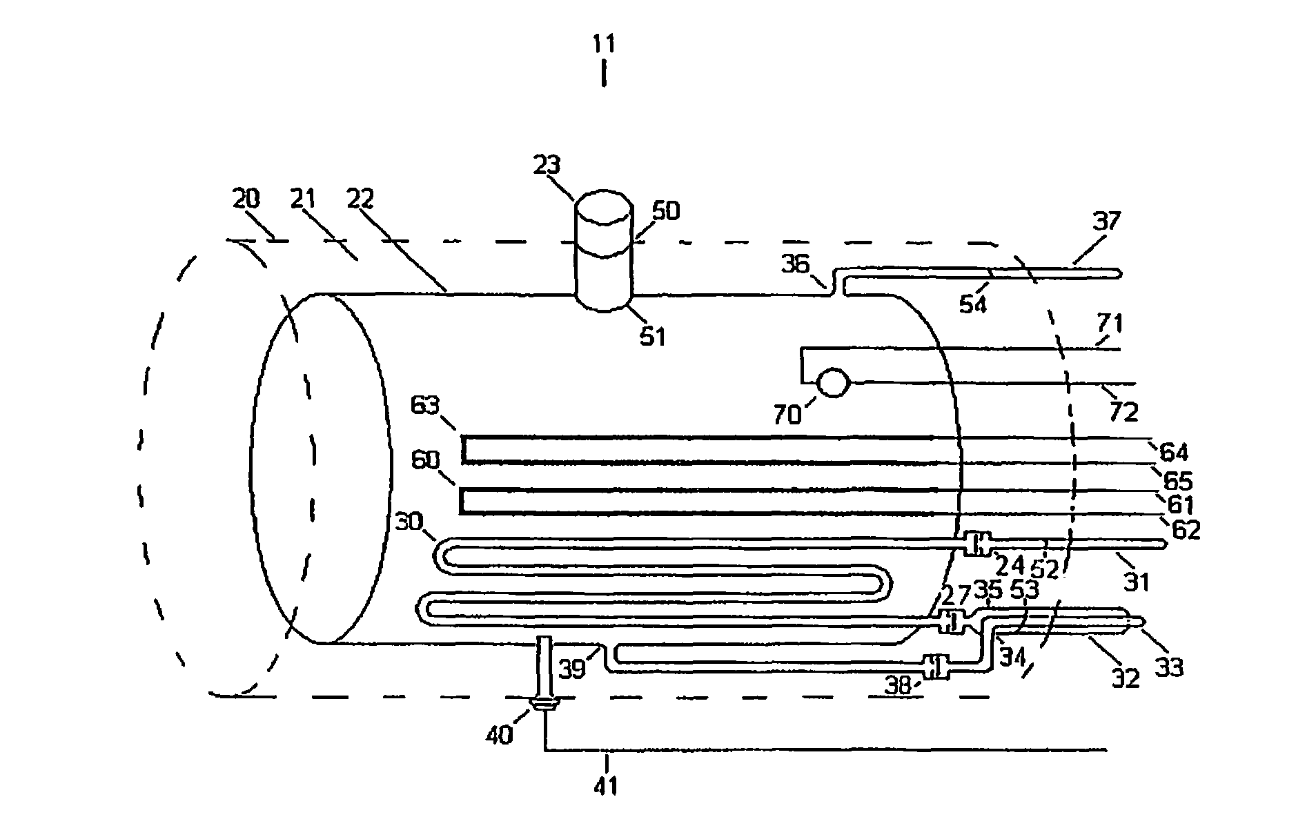
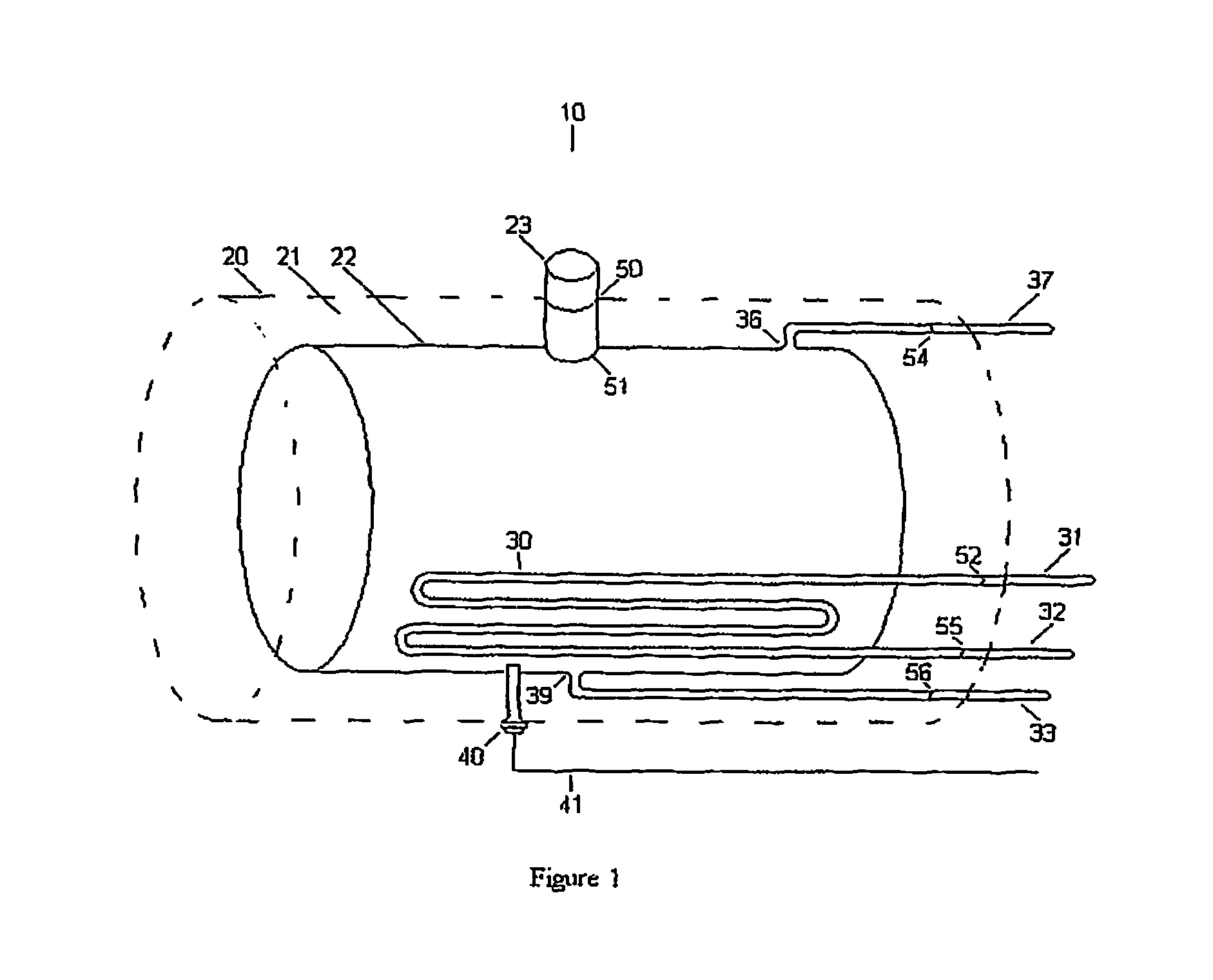
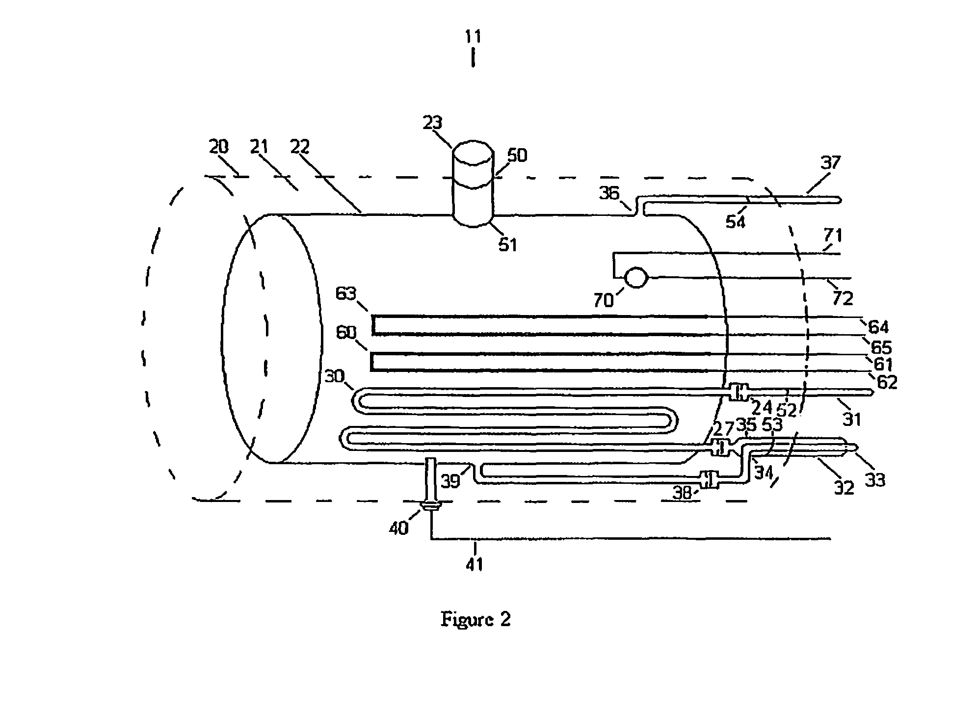
[0020]The present inventions now will be described more fully hereinafter with reference to the accompanying drawings, in which some, but not all embodiments of the inventions are shown. Indeed, these inventions may be embodied in many different forms and should not be construed as limited to the embodiments set forth herein; rather, these embodiments are provided so that this disclosure will satisfy applicable legal requirements. Like numbers refer to like elements throughout.

[0021]Unless otherwise defined, all terms (including technical and scientific terms) used herein have the same meaning as commonly understood by one of ordinary skill in the art to which this invention belongs. It will be further understood that terms, such as those defined in commonly used dictionaries, should be interpreted as having a meaning that is consistent with their meaning in the context of the relevant art and will not be interpreted in an idealized or overly formal sense unless expressly so defined...


PUM


Abstract

A fuel tank for storing an alternate fuel and providing the fuel to an internal combustion engine includes: an inner shell with an internal cavity designed to store fuel; an outer shell configured and positioned relative to the inner shell such that an interstitial volume is created between the inner and outer shells; and a heating unit positioned in the interstitial volume. In some embodiments, the interstitial volume is filled with air; in other embodiments, the interstitial volume is filled with a thermally insulative material.

Description

RELATED APPLICATION[0001]This application claims priority to U.S. Provisional Patent Application No. 60 / 747,811, filed May 21, 2006, the disclosure of which is hereby incorporated herein in its entirety.FIELD OF THE INVENTION[0002]The present invention relates to fuel systems for internal combustion engines and more particularly to fuel systems that provide an alternate fuel to an internal combustion engine.BACKGROUND OF THE INVENTION[0003]For a variety of reasons, most of which relate to environmental and alternative energy pursuits, certain primary fuel engines, such as diesel engines, can be made to accommodate alternate fuels, such as straight vegetable oil (SVO), “biodiesel,” and other fuel oils (hereinafter “alternate fuels”). However, practical applications have demonstrated that alternate fuel should be heated up to a temperate that will allow it to easily pass through the fuel delivery system. Likewise, if left in a storage tank to cool, the alternate fuel has a tendency to...

Claims


Application Information

Patent Timeline
04 Sep 2012
Publication
US8256401B2
IPC
F02M31/16
CPC
F02M31/10; F02M31/125; F02M37/0064; Y02T10/126; Y02T10/12
Inventors
PAYNE, EDWARD A.; WILLIAMS, RODGER KARL