Stent retention element and related methods

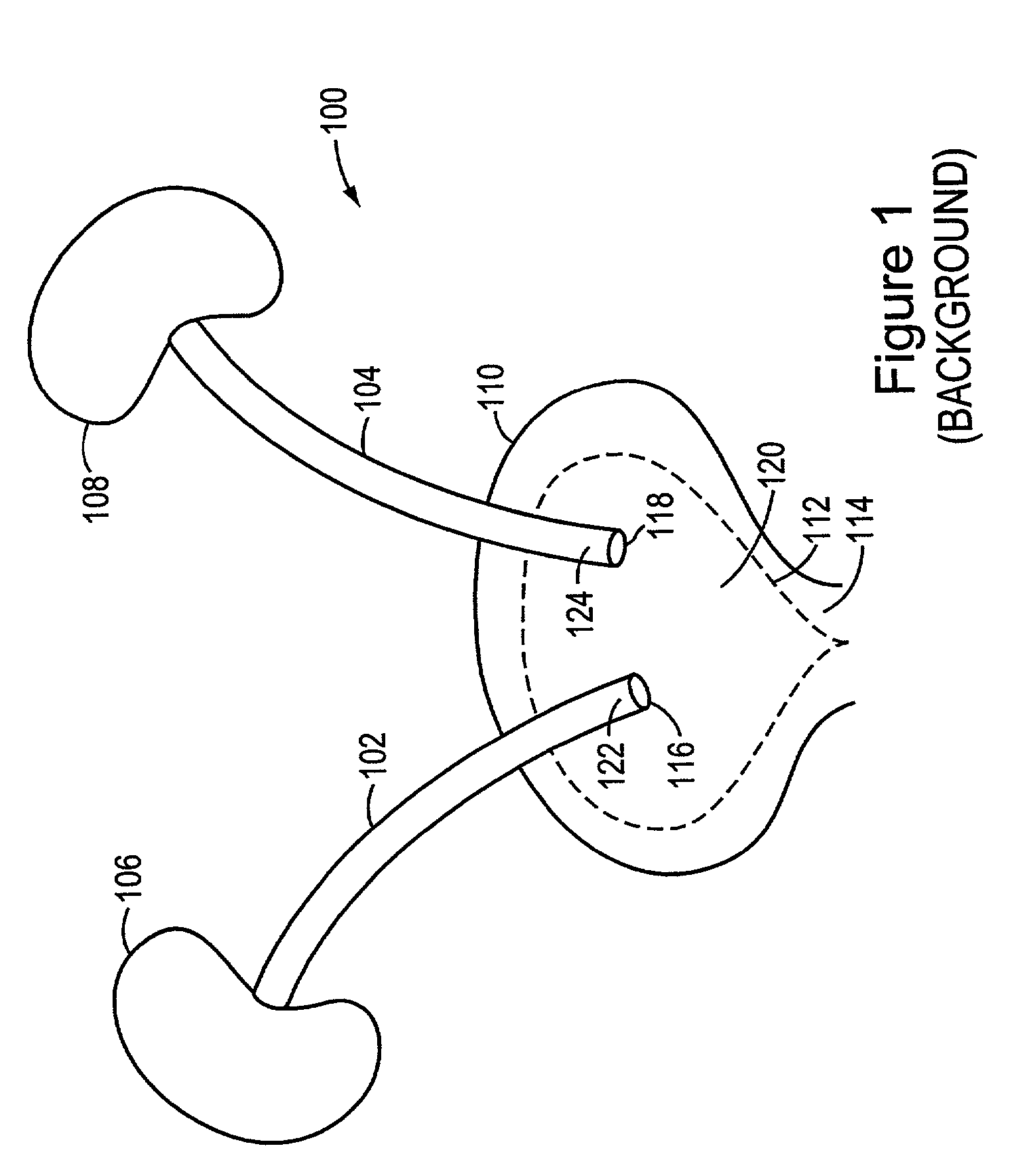
a technology of stent and ureter, which is applied in the field of stents, can solve the problems of force compression or constriction of the ureter, blockage of the ureter, and the need for sufficient length, and achieve the effect of reducing patient irritation

Active Publication Date: 2012-12-11
BOSTON SCI SCIMED INC
View PDF287 Cites 35 Cited by
  • Summary
  • Abstract
  • Description
  • Claims
  • Application Information

AI Technical Summary

Problems solved by technology

Also, a tumor growing against the outer wall of the ureter can force compression or constriction of the ureter.
A tumor on the internal ureteral wall can also cause blockage of the ureter.
One drawback of such conventional stents, is that typically, they need to be of sufficient length to allow for some relative movement between the kidney 106 and the urinary bladder 110, due to, for example, patient movement or peristaltic action, without becoming dislodged.

Method used


Image

  • Stent retention element and related methods
  • Stent retention element and related methods
  • Stent retention element and related methods

Examples


Embodiment Construction

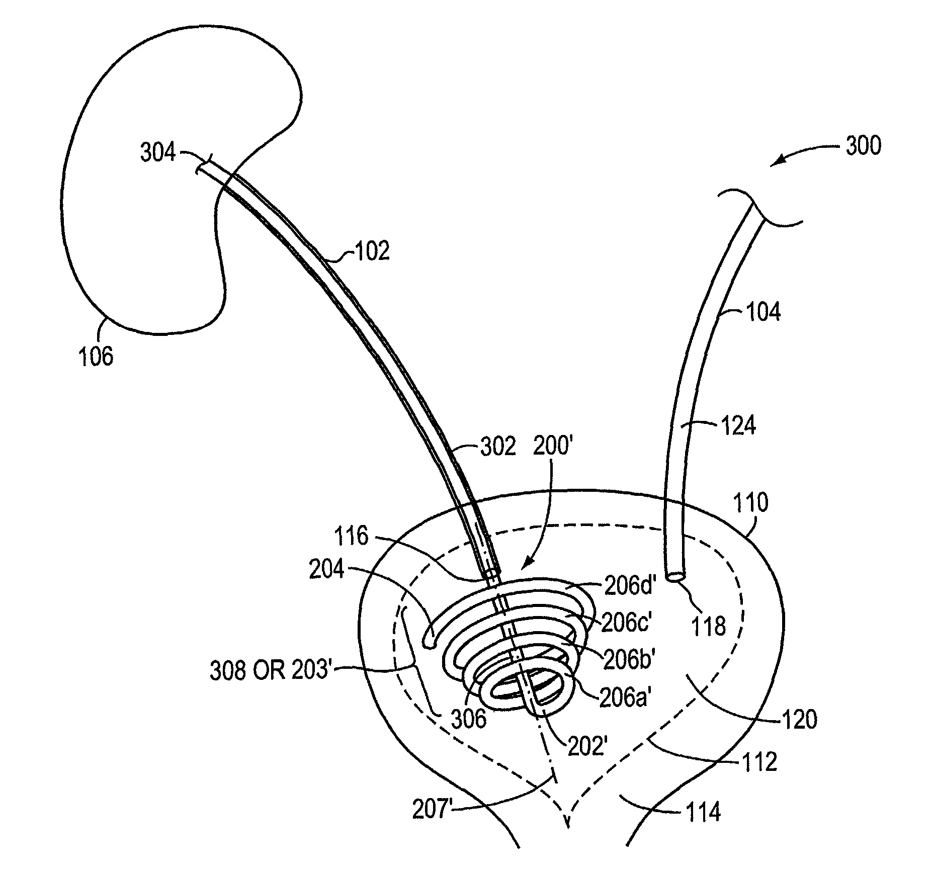
[0034]As described above in summary, the invention relates generally to stents. More particularly, in one embodiment, the invention is directed to a stent retention element. In further embodiments, the invention is directed to a ureteral stent having a retention element adapted to accommodate both ureter lengthening and shortening, while reducing patient discomfort and inhibiting stent migration.

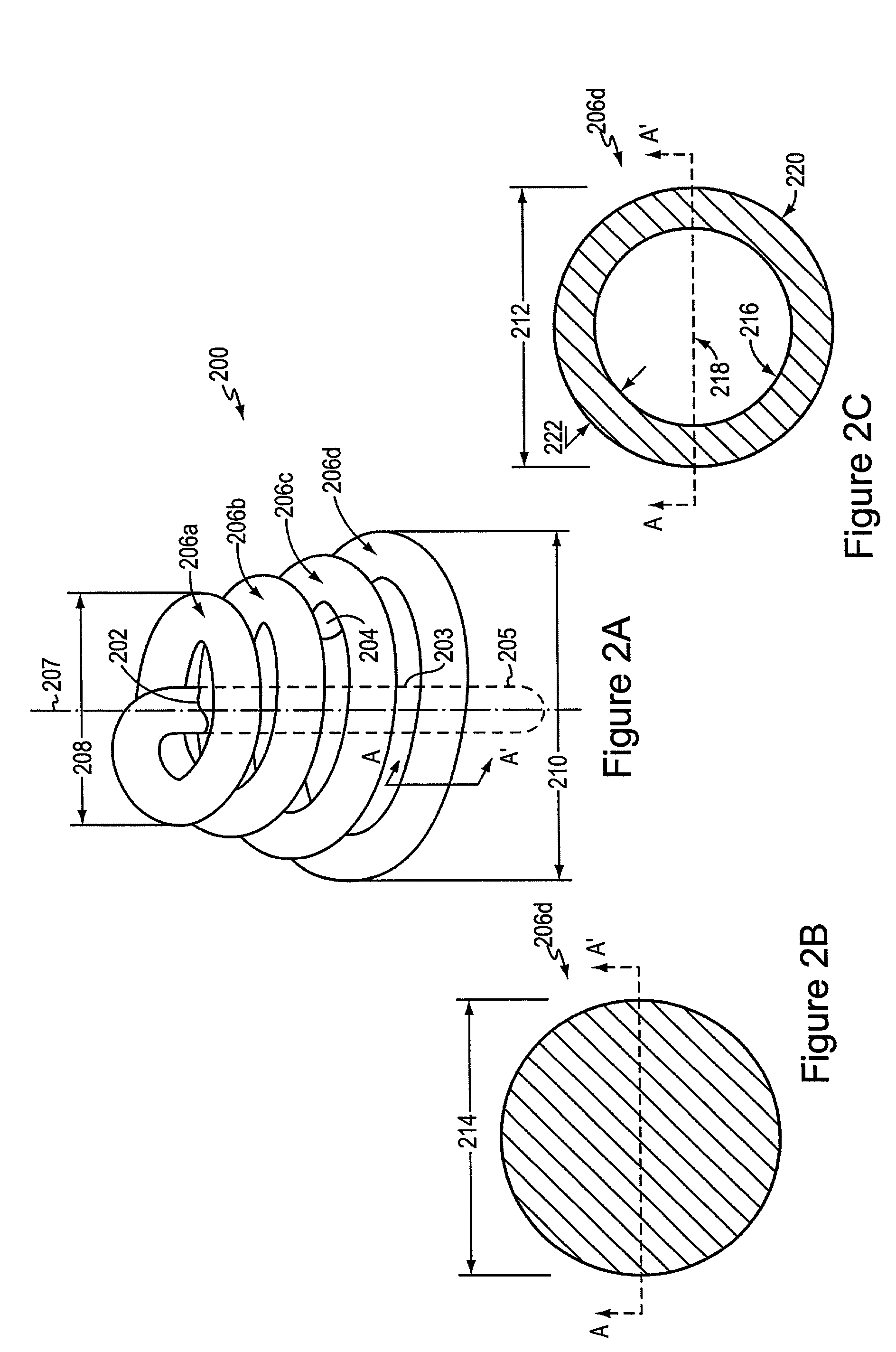
[0035]FIG. 2A is a side perspective view of a retention element 200 according to an illustrative embodiment of the invention. The retention element 200 includes an elastic member 206 and optionally, an elongate section 203. The elastic member 206 includes a plurality of coils 206a-206d coiling at a distance around a substantially central axis 207 from a first end 202 of the elastic member 206 to a second end 204 of the elastic member 206. Illustratively, the coils 206a-206d are formed, at least in part, from an elastic or super elastic material having shape retention features to enable the r...


PUM


Abstract

In one embodiment, the invention is directed to a stent retention element having an elastic member adapted to be incorporated with a first end of an elongate stent and to coil toward a second end of the elongate stent to anchor the elongate stent at an anatomical site. According to one feature, the stent retention element expands and compresses to effectively lengthen and shorten, respectively, the stent to accommodate ureter lengthening and shortening.

Description

TECHNICAL FIELD[0001]This invention generally relates to stents. More particularly, in one embodiment, the invention is directed to a stent retention element.BACKGROUND OF THE INVENTION[0002]A stent is a medical device adapted for propping open an obstructed passage within the body, such as a blocked ureter. In general, ureteral blockage is a medical condition requiring treatment. A ureteral blockage can occur for a number of reasons, including the passage of a kidney stone and / or other material into the ureter where it becomes entrapped. Also, a tumor growing against the outer wall of the ureter can force compression or constriction of the ureter. A tumor on the internal ureteral wall can also cause blockage of the ureter. Ureteral stents are often used to correct such problems. A ureteral stent may be placed inside the ureter on a temporary basis to allow proper drainage of fluids from the kidney to the urinary bladder. One end of a typical ureteral stent is placed in the kidney a...

Claims


Application Information

Patent Timeline
Patent Type & Authority Patents(United States)
IPC IPC(8): A61F2/04A61M25/00
CPCA61M27/008A61F2002/048
Inventor GELLMAN, BARRY N.
Owner BOSTON SCI SCIMED INC
Why Eureka
Try Eureka