Tampon applicator assembly

a technology of applicator and applicator body, which is applied in the field of tampon applicator assembly, can solve the problems of affecting the delivery of tampon, affecting the proper and comfortable delivery of tampon, and user's use of excessive gripping force on the barrel, etc., and achieves the effect of convenient use, easy gripping and control

Active Publication Date: 2013-02-12
PLAYTEX PROD INC
View PDF45 Cites 15 Cited by
  • Summary
  • Abstract
  • Description
  • Claims
  • Application Information

AI Technical Summary

Benefits of technology

[0009]It is an object of the present invention to provide an easy to use tampon applicator assembly, which is easy to grip and control during insertion and removal of the applicator assembly, as well as during expulsion of the pledget.
[0010]It is another object to provide a tampon applicator assembly having petals with a length-to-width ratio that facilitates expulsion of the pledget.
[0012]It is a further object of the present invention to provide a tampon applicator assembly having a barrel with tapered tip and a tapered main section, which facilitates insertion and removal of the applicator assembly.
[0013]It is still a further object of the present invention to provide a tampon applicator assembly having a barrel with a finger grip having a shoulder and a flare, which facilitates insertion and removal of the applicator assembly.

Problems solved by technology

Accordingly, an assembly that is difficult to grip and control can hinder proper and comfortable delivery of the pledget.
Another problem associated with a difficult to grip and control assembly is that the user often applies excessive gripping force on the barrel to compensate for the lack of gripability.
This excessive force may partially deform and damage the barrel and / or plunger, thereby distorting the assembly and obstructing the normal pathway of the pledget therefrom.
As a result, the user may be required to apply a significant amount of force to eject the pledget from the assembly, which may result in discomfort to the user.

Method used


Image

  • Tampon applicator assembly
  • Tampon applicator assembly
  • Tampon applicator assembly

Examples


Embodiment Construction

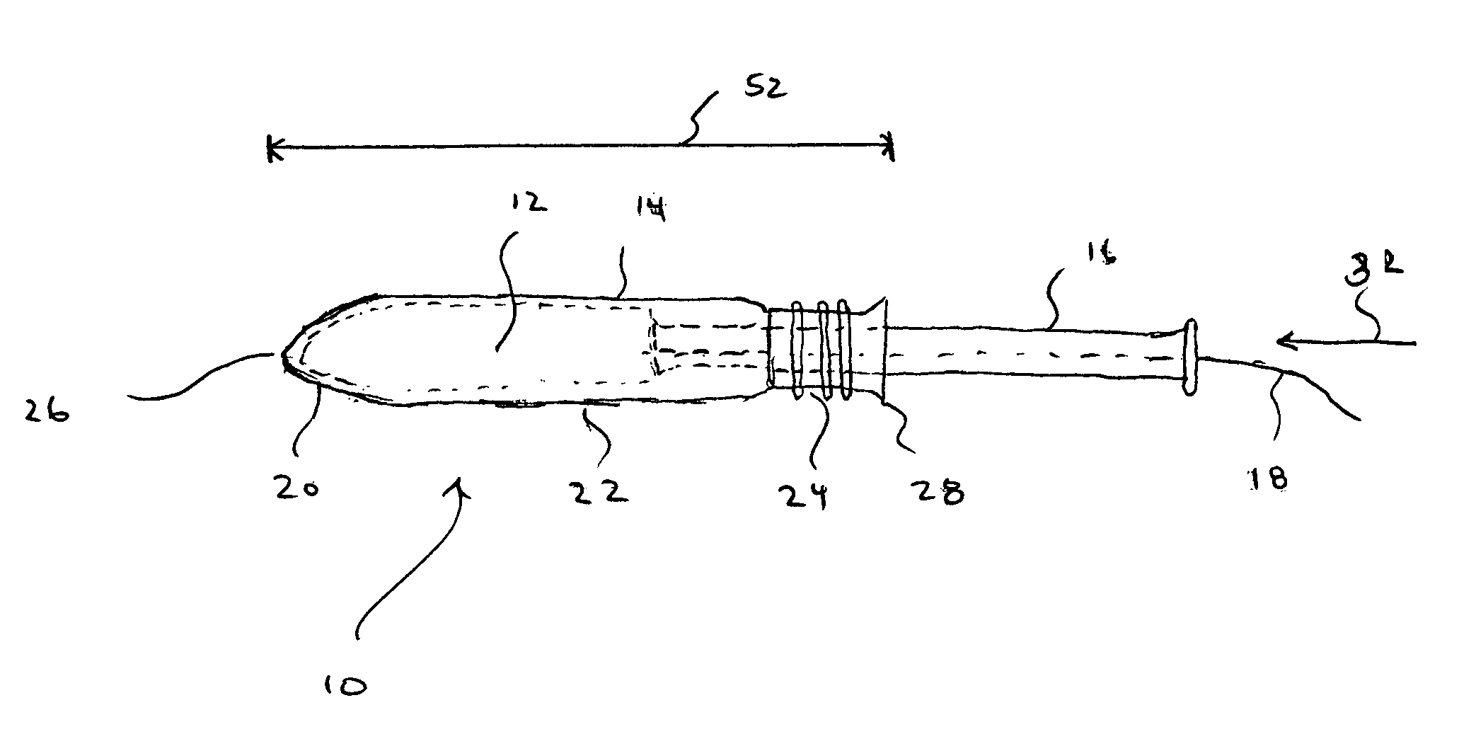
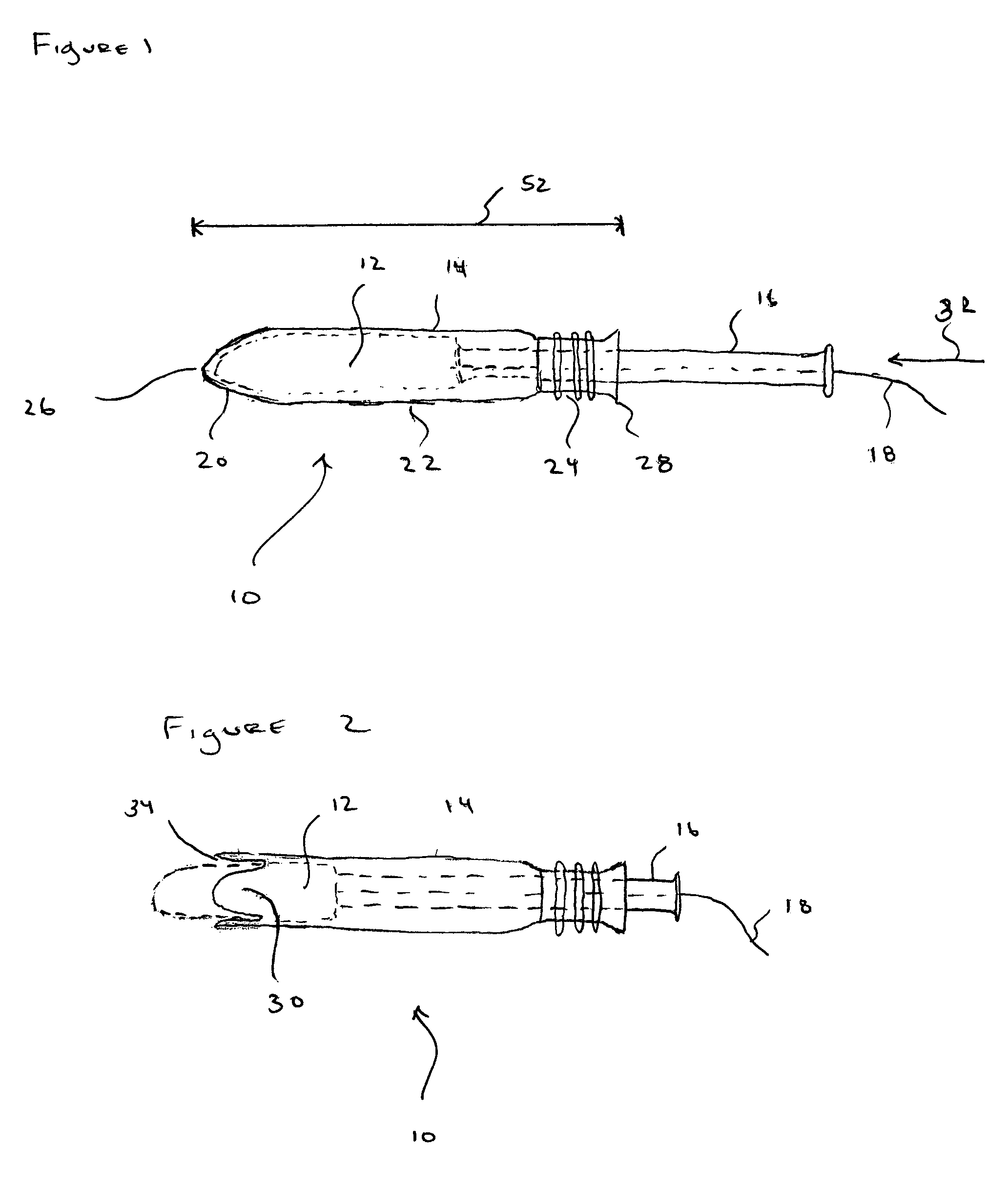
[0025]Referring now to the figures and more particularly to FIGS. 1 and 2, an exemplary embodiment of an improved tampon applicator assembly generally represented by reference numeral 10 is illustrated. The improved assembly 10 is easier to insert, use, and remove than prior tampon applicator assemblies.

[0026]Assembly 10 has a pledget 12, a barrel 14, and a plunger 16. Pledget 12 is disposed in barrel 14. Pledget 12 has a withdrawal cord 18 connected thereto, which extends through barrel 14 and plunger 16, and out of assembly 10.

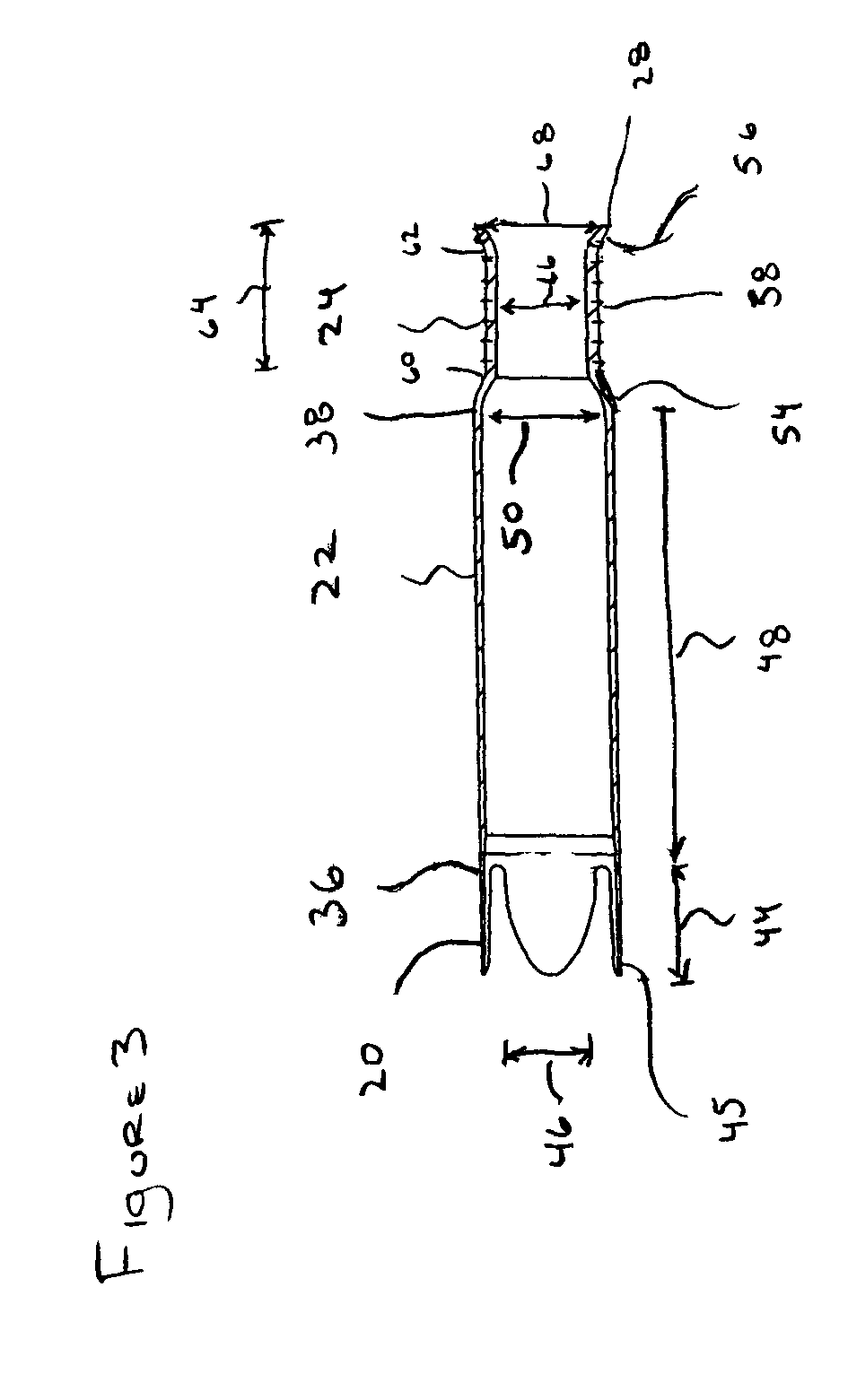
[0027]Barrel 14 is sub-divided into three sections, namely an insertion tip 20, a main section 22, and a finger grip 24. Insertion tip 20 defines a first end 26 of barrel 14, while finger grip 24 terminates at a second end 28 of the barrel.

[0028]Plunger 16 can expel pledget 12 from barrel 14. For example, first end 26 can have a number or a plurality of petals 30 disposed about the end. Petals 30 open as shown in FIG. 2 upon application of a predetermined ex...


PUM


Abstract

A tampon applicator assembly having a barrel, a plunger, and a pledget is provided. The barrel has an insertion tip, a main section, and a finger grip. The main section can have a maximum outer dimension located closer to the finger grip than to the insertion tip and / or can have a main section taper ratio of about 1.07 to about 1.15. The insertion tip can have a taper ratio of more than about 0.66 and / or a plurality of petals with a petal length-to-width ratio over about 2 to less than about 3.

Description

CROSS-REFERENCE TO RELATED APPLICATIONS[0001]This application is a continuation-in-part of U.S. application Ser. No. 10 / 407,855 filed on Apr. 4, 2003 now abandoned, the contents of which are incorporated by reference.BACKGROUND OF THE INVENTION[0002]1. Field of the Invention[0003]The present invention is related to a tampon applicator assembly. More particularly, the present invention is related to an improved tampon applicator assembly that increases the ease of use and user comfort.[0004]2. Description of Related Art[0005]A tampon applicator assembly is used to inject an absorbent or hygienic material, known as a tampon pledget, into a vaginal cavity. Commercial tampon applicator assemblies typically have a barrel and a plunger used to expel a pledget housed in the barrel.[0006]The use of such assemblies requires a user to grip the barrel and guide it easily into the vaginal cavity. This is particularly important since a portion or all of the assembly is out of a direct line of si...

Claims


Application Information

Patent Timeline
Patent Type & Authority Patents(United States)
IPC IPC(8): A61F13/20A61F13/26
CPCA61F13/26
Inventor LEMAY, JESSICA ELIZABETHEDGETT, KEITHJARMON, GEORGE S.BENNETT, KATHRYN
Owner PLAYTEX PROD INC
Why Eureka
Try Eureka