Segmented antenna reflector with shield

a technology of segmented reflectors and shields, which is applied in the field of segmented reflector antennas with shields, can solve the problems of shape errors in assembled reflectors, wind load, manufacturing/assembly complexity,

Inactive Publication Date: 2013-03-26
COMMSCOPE TECH LLC
View PDF20 Cites 3 Cited by
  • Summary
  • Abstract
  • Description
  • Claims
  • Application Information

AI Technical Summary

Benefits of technology

[0028]The proximal portion 14 of each peripheral segment 6 preferably couples to the peripheral coupling portion 12 on both a proximal side 20 and a distal side 22 of the reinforcing portion 18, significantly improving a rigidity characteristic of the assembled antenna reflector 2. The coupling may be via, for example, fasteners such as screws, bolts or the like, applied in two rings generally concentric with the periphery of the reflector dish 16 along each side of the reinforcing portion 18.
[0032]The central segment 4 and peripheral segment(s) 6 may be manufactured with a high level of precision via metal stamping, with material cost and overall weight savings by the application of a thicker gauge of material to the central segment 4, than the peripheral segment(s) 6, as the central segment significantly reinforces the peripheral segment(s) 6 and also bears the stress of supporting additional equipment and / or mounting hardware of the antenna assembly. Further, the peripheral segment 6 incorporating both reflector portion 8 and shield portion 10 provides an additional circumferential band integral with but at an angle to the reflector dish 16, which may improve the strength characteristics of the assembled antenna reflector 2.
[0033]During inventory and / or transportation, the antenna reflector 2 may be tightly packed, for example as shown in FIG. 11, into a package primarily constrained by the diameter of the central segment 4, which results in a package dimension much less than a traditional unitary body reflector dish reflector antenna configuration. During installation, especially in remote areas, the small package enables ease of transport and site delivery where traditional motor transport may not be available. Also, field assembly of the antenna reflector 2 is greatly simplified, for example as shown in FIGS. 12 and 13, because the various flanges and tabs may be applied in self aligning fashion and a significant amount of hardware for the prior separate attachment of a shield assembly to the reflector dish periphery may be eliminated.

Problems solved by technology

Although smaller reflector segments improve the portability of the resulting antenna, each additional segment interconnection introduces the opportunity for shape errors in the assembled reflector due to cumulative misalignment and / or warping of the individual segments.
A shield adds to the weight, wind load and manufacture / assembly complexity of the resulting reflector antenna assembly.

Method used


Image

  • Segmented antenna reflector with shield
  • Segmented antenna reflector with shield
  • Segmented antenna reflector with shield

Examples


Embodiment Construction

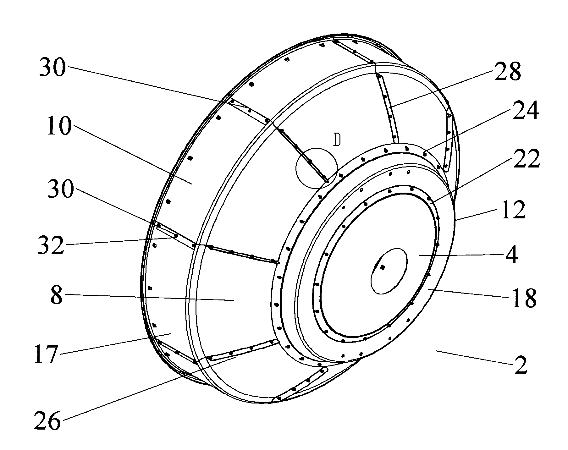
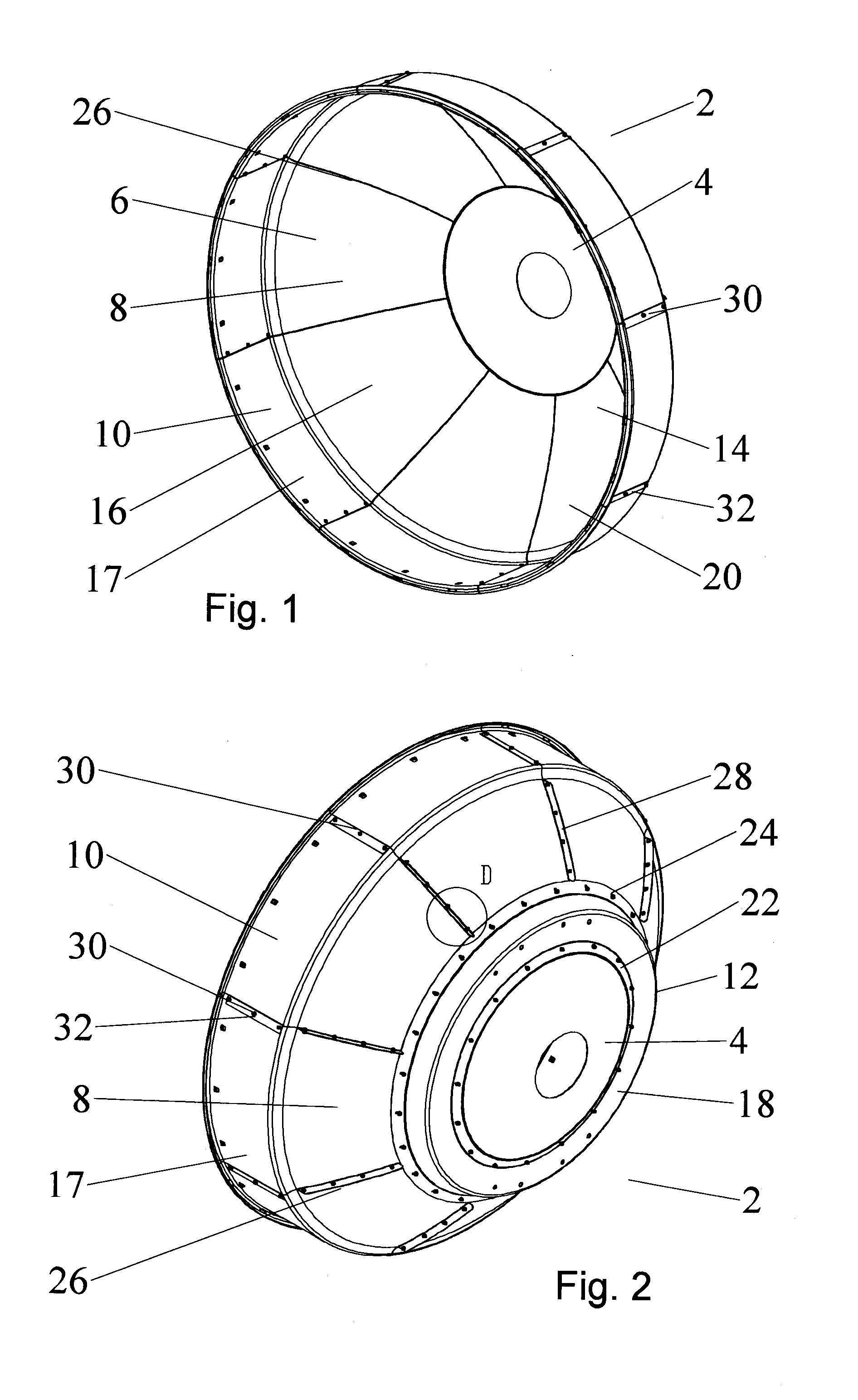
[0023]In the exemplary embodiments herein, the segmented antenna reflector is demonstrated as a generally parabolic circular dish reflector surface for use in, for example, a reflector antenna for terrestrial point-to-point microwave communications. Alternatively, one skilled in the art will recognize that the reflector segment(s) may be formed in a range of other shapes and configurations, for example generally rectangular or elliptical, to form a reflector surface with an alternative shape, such as a planar reflector or an inner or outer toroidal section.

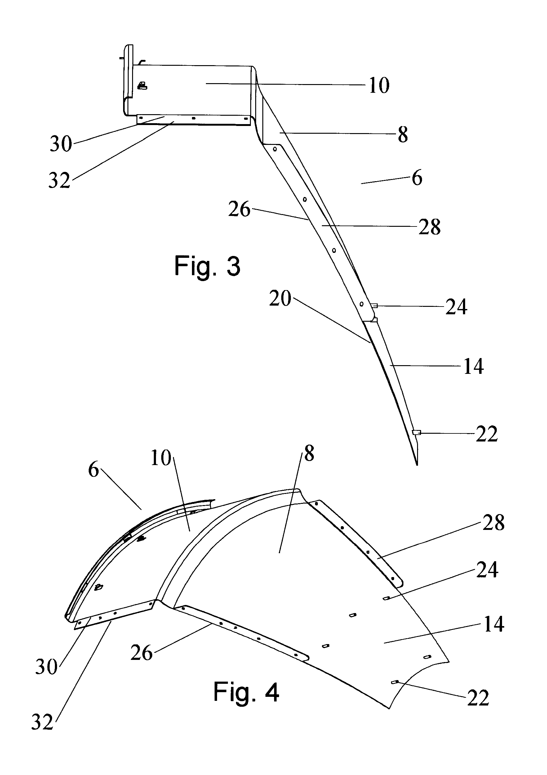
[0024]A first exemplary embodiment of a segmented antenna reflector 2, comprising a central segment 4 with a plurality of peripheral segment(s) 6, each with a reflector portion 8 and a shield portion 10, will now be described with reference to FIGS. 1-2. The central segment 4 is provided with a peripheral coupling portion 12 to which a proximal portion 14 of each peripheral segment 8 is attached.

[0025]The reflector portion(s) 8 ar...


PUM

PropertyMeasurementUnit
diameteraaaaaaaaaa
thicknessaaaaaaaaaa
weightaaaaaaaaaa

Abstract

An antenna reflector includes a central segment with a peripheral coupling portion and a plurality of peripheral segments, each provided with a reflector portion and a shield portion. A proximal portion of each shield portion is dimensioned to couple with the peripheral coupling portion, a reflector portion edge of each peripheral segment is dimensioned to couple with adjacent reflector portion edges and a shield portion edge of each peripheral segment is dimensioned to couple with adjacent shield portion edges. The central segment and the reflector portion of the peripheral segments together form a reflector dish. The shield portions together provide a circumferential shield extending from a periphery of the reflector dish along an antenna boresight of the reflector dish.

Description

BACKGROUND[0001]1. Field of the Invention[0002]This invention relates to reflector antennas. More particularly, the invention relates to a segmented reflector antenna with a shield incorporated with peripheral segments of the reflector dish.[0003]2. Description of Related Art[0004]Reflector Antennas utilize a reflector to concentrate signals upon a subreflector and / or feed assembly. A large reflector concentrates weak signals, enabling low power, high bandwidth signal communications.[0005]Large reflectors may be formed from a plurality of segments that are interconnected to form the desired reflector surface. Although smaller reflector segments improve the portability of the resulting antenna, each additional segment interconnection introduces the opportunity for shape errors in the assembled reflector due to cumulative misalignment and / or warping of the individual segments.[0006]A shield extending forward of the reflector dish may be applied to improve the antenna signal pattern an...

Claims


Application Information

Patent Timeline
Patent Type & Authority Patents(United States)
IPC IPC(8): H01Q15/14
CPCH01Q15/166H01Q1/12H01Q1/526Y10T29/49016Y10T29/49826
Inventor LEWRY, MATTHEWSIMMS, STEPHENBELL, STEVEN
Owner COMMSCOPE TECH LLC
Why Eureka
Try Eureka