Drive unit for garage doors with universal electric connection options

a technology of universal electric connection and drive unit, which is applied in the direction of door/window fittings, power supply, construction, etc., can solve the problems of unfavorable assembly and installation of assembly and installation of power for electric motors, and achieve the effects of low structural expenditure, low number of components, and easy supply

Inactive Publication Date: 2013-06-18
SOMMER ANTRIEBS & FUNKTECHNIK GMBH
View PDF14 Cites 2 Cited by
  • Summary
  • Abstract
  • Description
  • Claims
  • Application Information

AI Technical Summary

Benefits of technology

[0006]It is therefore the object of the present invention to provide a drive unit of the aforementioned type, which makes it possible to realize an easily established and universally usable contact to external units.
[0009]The plug connectors according to the invention provide a flexible and quickly established option for connecting the drive unit traversing inside the carriage.
[0011]According to one advantageous embodiment of the invention, electrical spring-loaded contacts as components of the electrical plug connectors are integrated into a connecting housing, which can be fitted onto the guide rail to make contact with the electrical contacts provided thereon. With this type of contacting, power can be supplied easily to the guide element and the guide rail and thus to the traversing drive unit inside the carriage.
[0015]Since both variants are provided with the same electrical connection and are also embodied identical with respect to the mechanical interface parameters, the connecting housings of these variants can be exchanged easily and quickly in order to modify a connection configuration.
[0017]For this embodiment, an electrical contact is exposed on one wall of the insert element, which makes contact with to an electrical spring-loaded contact of the connecting housing once the connecting housing is fitted onto the guide rail with therein disposed insert element, thereby establishing the conducting connection to the guide element. A planned second electrical spring-loaded contact is advantageously fitted directly onto the guide rail when sliding on the connecting housing. As a result, the guide rail and the guide elements can be connected to an external power supply using a very low number of components and extremely low structural expenditure. Power can thus be supplied easily and with little expenditure to the drive unit via the guide element and the guide rail.

Problems solved by technology

The electrical contact, embodied in this way, for supplying power to the electric motor requires an undesirably high expenditure for the assembly and installation.

Method used


Image

  • Drive unit for garage doors with universal electric connection options
  • Drive unit for garage doors with universal electric connection options
  • Drive unit for garage doors with universal electric connection options

Examples


Embodiment Construction

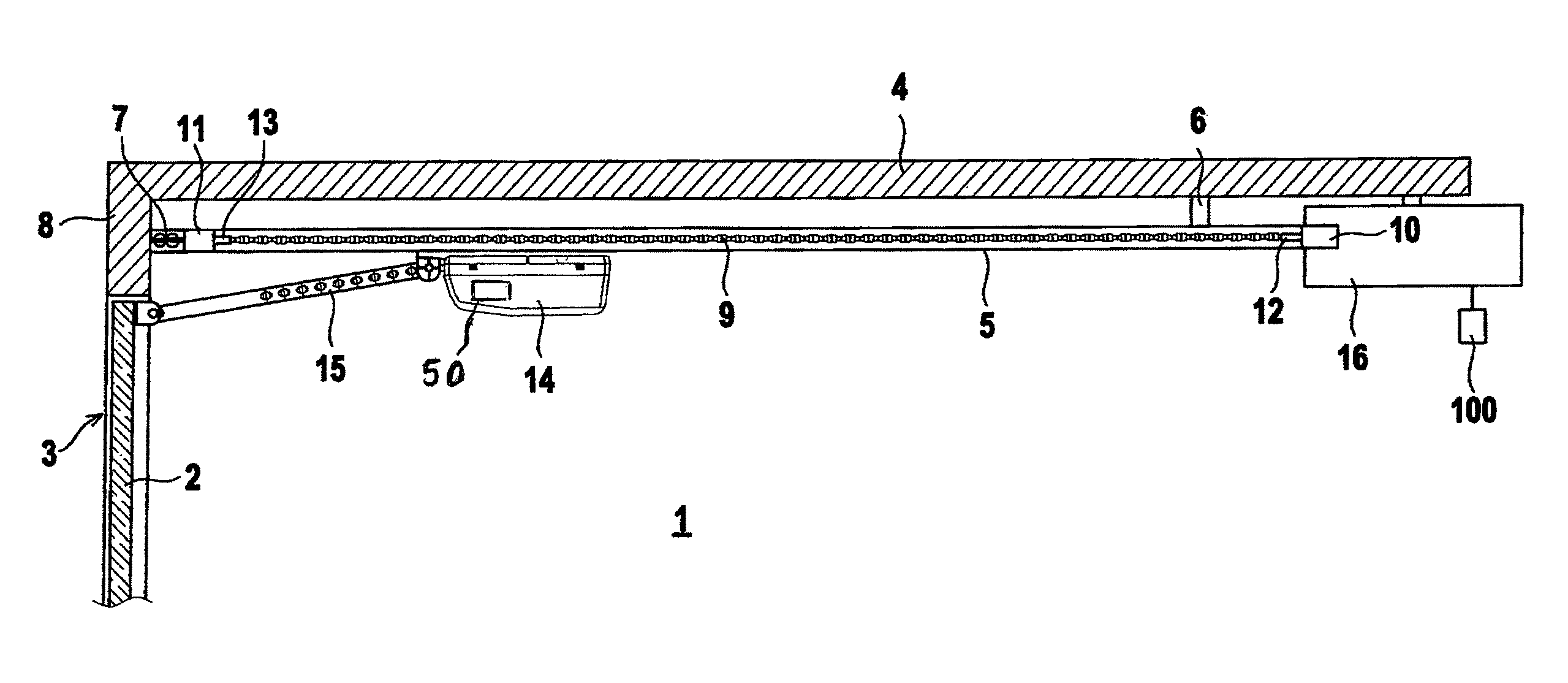
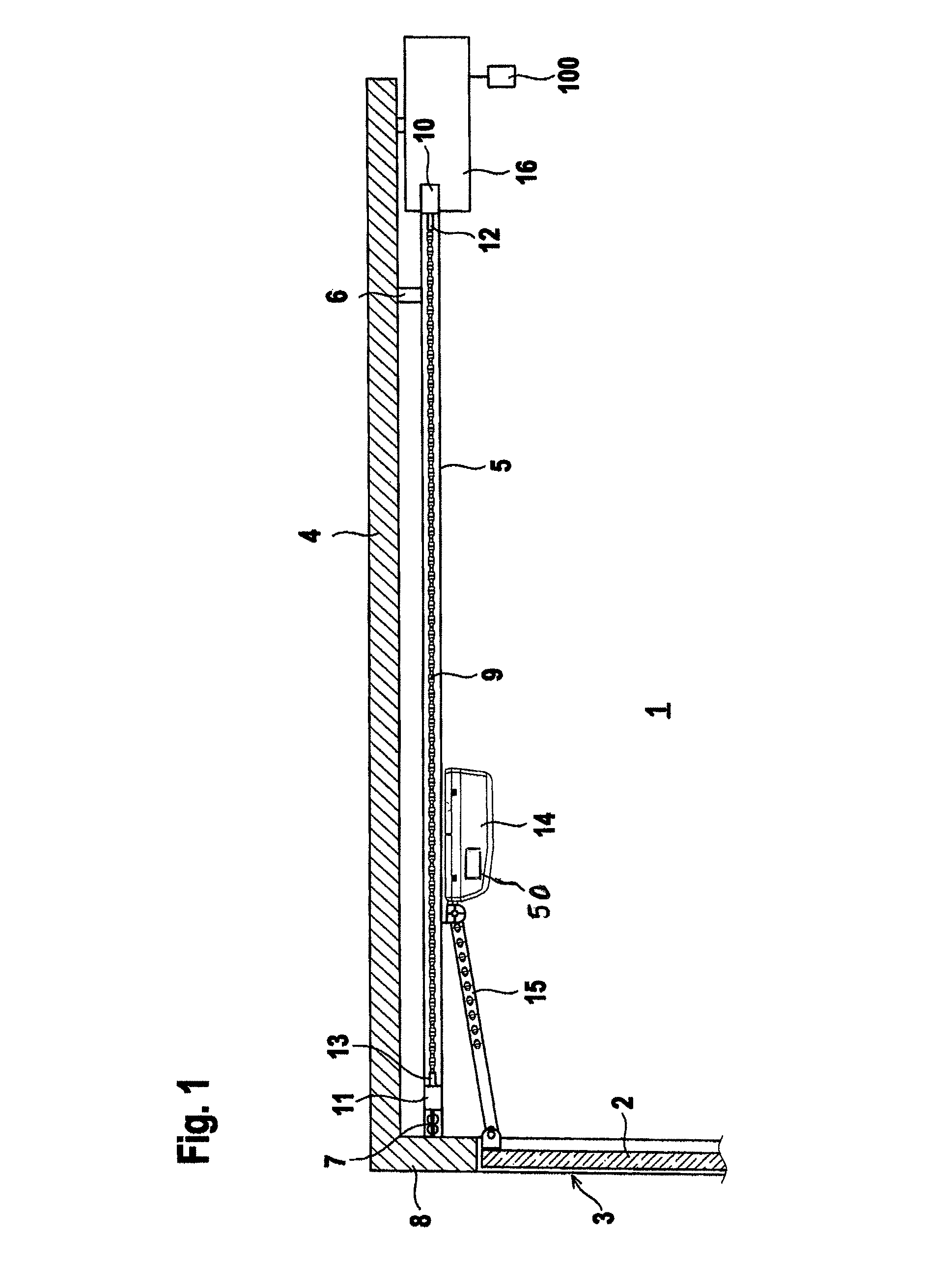
[0022]FIG. 1 shows a first exemplary embodiment of a drive unit 1 for a door, wherein this door in the present case is a garage door 2. FIG. 1 shows a longitudinal section through the garage door 2 in the closed state, in which it is located inside a door opening 3 in a garage wall. In this closed state, the plane for the garage door 2 extends in a vertical plane and closes off the door opening 3.

[0023]The drive unit 1 is used to operate the garage door 2, wherein this door can be moved between an open position and a closed position. In the open position, the garage door 2 is arranged below the garage ceiling 4, thereby exposing the door opening 3.

[0024]A guide rail 5 that is mounted directly below the ceiling 4 of the garage is provided as a component of the drive unit 1. The guide rail 5 is attached in this case with holders 6, 7 to the ceiling 4, as well as to a lintel 8 that adjoins the ceiling 4 and delimits the garage door opening 3 on the top.

[0025]The guide rail 5 is embodie...


PUM


Abstract

A drive unit for a door includes a guiding device comprising guide rail and a guide element extending in a movement direction of the door. A drive device arranged inside a carriage moves back and forth along the guide rail and is engaged in the guide element. The drive unit is supplied with power via the guide rail and the guide element. Electrical plug connectors are provided on an external power source for the electrical connection of the guide element and the guide rail.

Description

CROSS-REFERENCE TO RELATED APPLICATIONS[0001]This application is a National Stage Application of PCT / EP2006 / 012210, filed Dec. 19, 2006, which designates the United States and claims the priority of German Application No. 10 2006 001 892, filed Jan. 14, 2006.BACKGROUND OF THE INVENTION[0002]The invention relates to a drive unit for a door.[0003]A drive unit of this type is know from the German Patent Application DE 102 27 110 A1. This drive unit functions as a garage door drive. As a component of the drive unit, a guide rail with therein disposed guide element in the form of a tensioned chain is mounted on the garage ceiling. A carriage can be moved back and forth along the guide rail with the aid of an electric motor, wherein the electric motor engages via a toothed gear in the chain. The carriage itself is connected is hinged with the aid of a rod to a door panel. The electric motor is controlled with the aid of an external control unit. Depending on the drive, the electric motor ...

Claims


Application Information

Patent Timeline
Patent Type & Authority Patents(United States)
IPC IPC(8): E05D15/38E05F15/10
CPCE05F15/67E05F15/668E05Y2201/434E05Y2201/656E05Y2400/30E05Y2400/658E05Y2600/46E05Y2900/106E05Y2600/45
Inventor SOMMER, FRANKWEISSINGER, RALF
Owner SOMMER ANTRIEBS & FUNKTECHNIK GMBH
Why Eureka
Try Eureka