Tire inflating station and method for inflating tires

a technology of inflating station and tire, which is applied in the direction of functional valve type, liquid handling, packaging goods type, etc., can solve the problems of not jumping correctly into the seat of the tire bead, the configuration also involves quite considerable construction cost, and the size of the inflation bell is only suitable for a limited range of motor vehicle wheel sizes. , to achieve the effect of low maintenance and high inflation accuracy

Active Publication Date: 2013-12-24
SCHENCK ROTEC GMBH
View PDF6 Cites 2 Cited by
  • Summary
  • Abstract
  • Description
  • Claims
  • Application Information

AI Technical Summary

Benefits of technology

[0009]The object of the invention is to provide a tire inflating station of the specified type which is suitable for a large range of different tire sizes and can be produced in a cost-effective manner. The tire inflating station should allow high inflation accuracy, be reliable and require little maintenance. A further object of the invention is to provide an advantageous method for inflating tires.
[0011]The tire inflating station according to the invention is characterized by a simple, robust construction which allows it to be produced in a cost-effective manner. Instead of a plurality of inflation bells, a single, linearly displaceable member with a plurality of inflation rings is provided which can be guided and mounted at little expense and can be moved into the different working positions by a cost-effective, linear drive. The seal of the inflation ring connections with respect to the inflation opening of the inflation device can also be configured in a simple and economical manner. Control of the inflation pressure is not affected when the inflation ring is replaced.
[0012]If, according to a further proposal of the invention, the carrier plate of the tire inflating station is arranged such that it can be moved in the conveying direction of the transportation means, the further advantage of a small space requirement is provided, since the necessary movement space for the carrier plate is then located above the conveying means and does not require any additional space at the side next to the tire inflating station.
[0013]A further proposal of the invention provides that the inflation device is rigidly connected to the stand and the bearing means can be moved up to the inflation device. The advantage of this configuration is that no movable connections are required for the supply of air and the forces which arise during the inflation of a tire can be effectively dissipated. Thus, for example the carrier plate can be supported with its upper side against a counter bearing plate which is attached to the stand and serves as a base for the components of the inflation device.
[0014]According to a further proposal of the invention, the movement of the bearing means can be achieved by a plurality of preferably pneumatic lifting cylinders which are arranged on the stand and by which the bearing means can be moved in a preferably vertical direction, perpendicular to its sealing surface. An additional hydraulic brake cylinder supports the high forces acting on the bearing means and transfers them over a short distance to the stand. The bearing means preferably has a supporting plate with a planar supporting surface that forms at least part of the sealing surface.
[0015]A further proposal of the invention provides that the conveying means has conveyor belts which are positioned in grooves in the upper side of the supporting plate when the bearing means is moved towards the inflation device, the conveyor belts in the grooves tightly sealing the grooves and forming with their upper side a second part of the sealing surface. This configuration achieves in a simple manner a sealing of the tire on the side opposite the inflation ring. Since the supporting plate is undivided, it can be configured in a very robust and distortion-resistant manner. Expensive guides and drive means for moving divided receiving plates apart can be dispensed with.

Problems solved by technology

Should this happen, the inflation bell would obstruct the radial movement of the tire which could result in the tire bead not jumping correctly into its seat.
Thus, an inflation bell is only suitable for a limited range of motor vehicle wheel sizes.
In addition to a large axial overall length, this configuration also involves quite considerable construction costs.
This known arrangement too is relatively expensive.

Method used


Image

  • Tire inflating station and method for inflating tires
  • Tire inflating station and method for inflating tires

Examples


Embodiment Construction

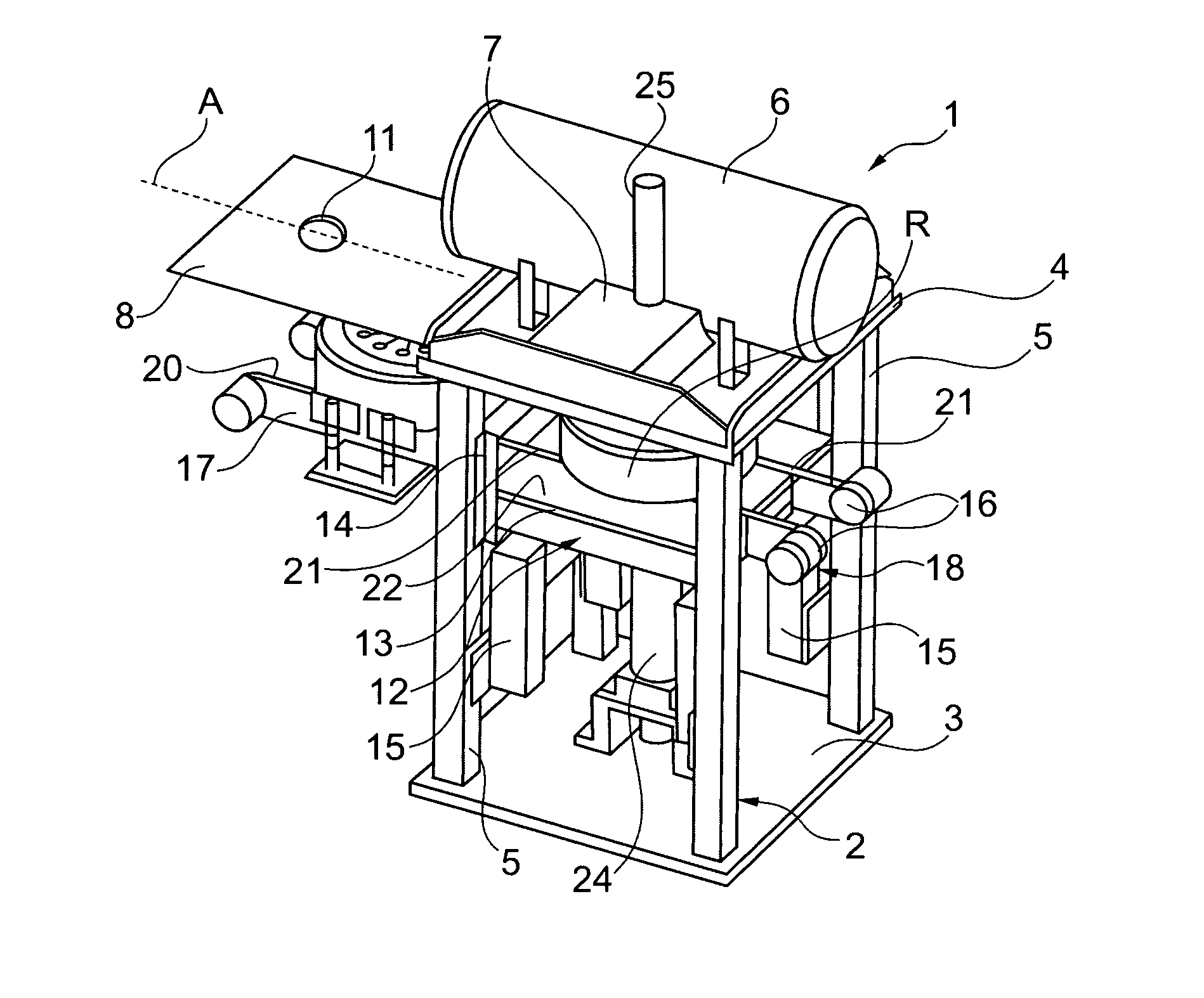
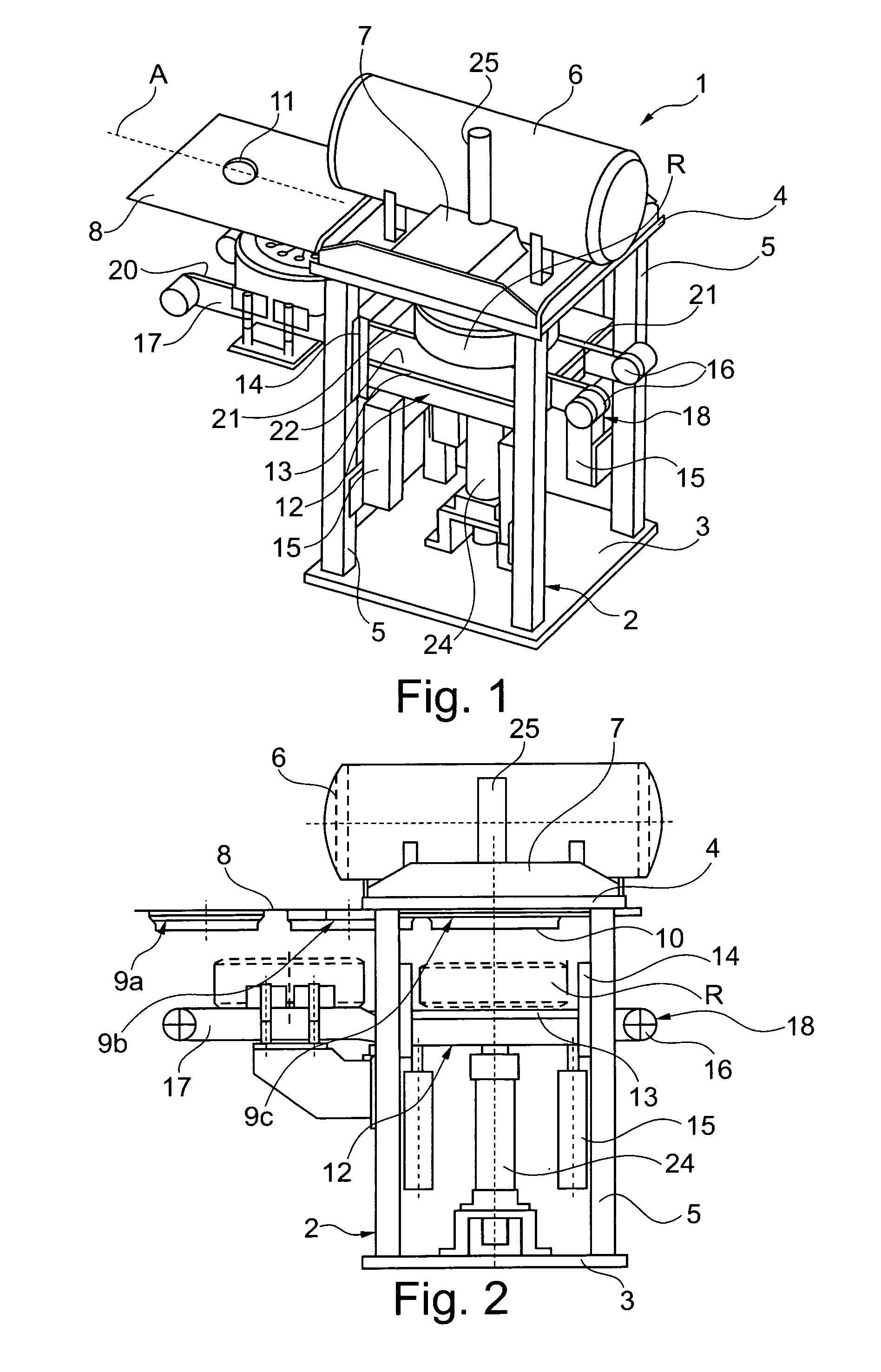
[0021]The tire inflating station 1 shown in the drawing has a stand 2 with a rectangular base plate 3 and a rectangular top plate 4 which are rigidly interconnected at their corners by four columns 5. Arranged on the top plate 4 are an air tank 6 and an inflation device 7, which has an inflation opening penetrating the top plate 4 and valves by which the inflation opening can be connected to the air tank 5 or to the atmosphere. A carrier plate 8 is mounted displaceably along an axis A parallel to the side edges of the top plate 4 on the lower side of the top plate 4 in a straight-line mechanism. In the direction of axis A, the carrier plate 8 has a length greater than that of the top plate 4. Its width is calculated such that it can be moved between the columns 5.

[0022]Positioned in tandem on the lower side of the carrier plate 8, seen in the longitudinal direction, are three inflation rings 9a, 9b, 9c of different diameters. The inflation rings 9a, 9b, 9c are arranged with spacing ...


PUM

PropertyMeasurementUnit
diametersaaaaaaaaaa
inflation pressureaaaaaaaaaa
diameteraaaaaaaaaa

Abstract

In a tire inflating station for inflating a tubeless tire arranged on a rim with a pressurized gas, arranged on a stand are a conveyor for receiving and conveying a wheel consisting of a wheel rim and a tire mounted on the wheel rim, and an inflation device above the conveyor and having an inflation opening which can be connected to a gas supply. The lower side of the inflation device has a carrier plate that is mounted to move backwards and forwards along an axis between at least two positions in a straight-line mechanism. There are inflation rings attached in tandem in a gas-tight manner to the lower side of a carrier plate. Inside the inflation rings, the carrier plate has a respective continuous opening. In each of the different working positions of the carrier plate, another of the continuous openings is connected to the inflation opening of the inflation device, which inflation opening is arranged on the upper side of the carrier plate.

Description

CROSS REFERENCE TO RELATED APPLICATIONS[0001]Applicants claim priority under 35 U.S.C. §119 of German Patent Application No. 10 2009 046 195.7 filed Oct. 30, 2009.BACKGROUND OF THE INVENTION[0002]1. Field of the Invention[0003]The invention relates to a tire inflating station and a method for inflating a tubeless tire arranged on a rim with a pressurized gas, comprising a stand, a conveying means which arranged on the stand for receiving and further conveying a wheel consisting of a wheel rim and a tire mounted on the wheel rim, an inflation device arranged above the conveying means and having an inflation opening which can be connected to a gas supply, and at least two inflation rings of different diameters which are configured to enter into sealing engagement with the upper side face of the tire of a wheel arranged lying under the inflation device. There is also a bearing means which has a sealing surface which cooperates with the lower side face of the tire and on which the wheel...

Claims


Application Information

Patent Timeline
Patent Type & Authority Patents(United States)
IPC IPC(8): B65B31/00
CPCB60C25/145B60S5/046Y10T137/3584B60C25/05B60C25/0512B60C25/0521B60C25/053B60S5/04B60S5/043
Inventor LEMSER, MATTHIASPEINELT, ANDREAS
Owner SCHENCK ROTEC GMBH
Why Eureka
Try Eureka