Soap dispensing units with anti-drip valve

a technology of anti-drip valve and soap dispenser, which is applied in the direction of liquid transfer devices, pliable tubular containers, instruments, etc., can solve the problems of loss of efficiency and lower total electrical energy required for soap dispensing, and achieve enhanced anti-drip and primability benefits, preventing unintended dripping, and easy prime

Active Publication Date: 2014-03-25
SIMPLEHUMAN
View PDF138 Cites 32 Cited by
  • Summary
  • Abstract
  • Description
  • Claims
  • Application Information

AI Technical Summary

Benefits of technology

[0006]An aspect of some of the embodiments disclosed herein includes the realization that in the art of discharge nozzles for viscous fluids, certain valves provide enhanced anti-drip and primability benefits over other valves. For example, some flap-type valves (e.g., reed valves, duckbill valves, or other valves that include a deflectable flap) tend to perform better in preventing unintended dripping from the discharge nozzle of a viscous fluid source, such as a liquid soap dispenser. Further, some valves can allow for the pump of a soap-dispensing system to be primed more easily yet still dispense the same amount or more soap with the same amount of energy as compared to soap pumps having different kinds of anti-drip valves.
[0008]Another aspect of certain embodiments disclosed herein includes the realization that certain types of valves, such as the flap-type valves discussed above, can allow a liquid soap dispenser system to be configured for easier pump priming. For example, in systems using flap-type valves, the high pressure side of the liquid soap pump can include a bypass passage directly connecting the discharge side to the associated liquid reservoir. In such a configuration, when the pump is at rest, the liquid soap from the reservoir can flow directly into the high pressure side of the pump and flow into the discharge side of the liquid soap discharge system. In some embodiments, the soap pump can remain primed at all times after the initial soap loading or at least between consecutive soap dispensing procedures. Such a passage also allows for some loss of efficiency when the soap pump is running; pressurized soap is forced back into the reservoir. However, even with such a loss of efficiency, the total electrical energy required for dispensing soap can be lower than that required for systems using other types of valves which require a higher soap pressure to open the valve.
[0011]In certain variants, the first and second deflectable members, when viewed along the slit, form a generally hourglass shape. The first and second deflectable members can be configured such that the generally hourglass shape increases the bias between the first and second deflectable members. In some embodiments, at least one of the first and second deflectable members further comprises a notch generally aligned with the slit. The notch can be configured to facilitate overcoming the bias of the first and second deflectable members.

Problems solved by technology

Such a passage also allows for some loss of efficiency when the soap pump is running; pressurized soap is forced back into the reservoir.
However, even with such a loss of efficiency, the total electrical energy required for dispensing soap can be lower than that required for systems using other types of valves which require a higher soap pressure to open the valve.

Method used


Image

  • Soap dispensing units with anti-drip valve
  • Soap dispensing units with anti-drip valve
  • Soap dispensing units with anti-drip valve

Examples


Embodiment Construction

[0067]A variety of soap dispensers are described below to illustrate various examples that may be employed to achieve one or more desired improvements. These examples are only illustrative and not intended in any way to restrict the general inventions presented and the various aspects and features of these inventions. Furthermore, the phraseology and terminology used herein is for the purpose of description and should not be regarded as limiting. No features, structure, or step disclosed herein is essential or indispensible.

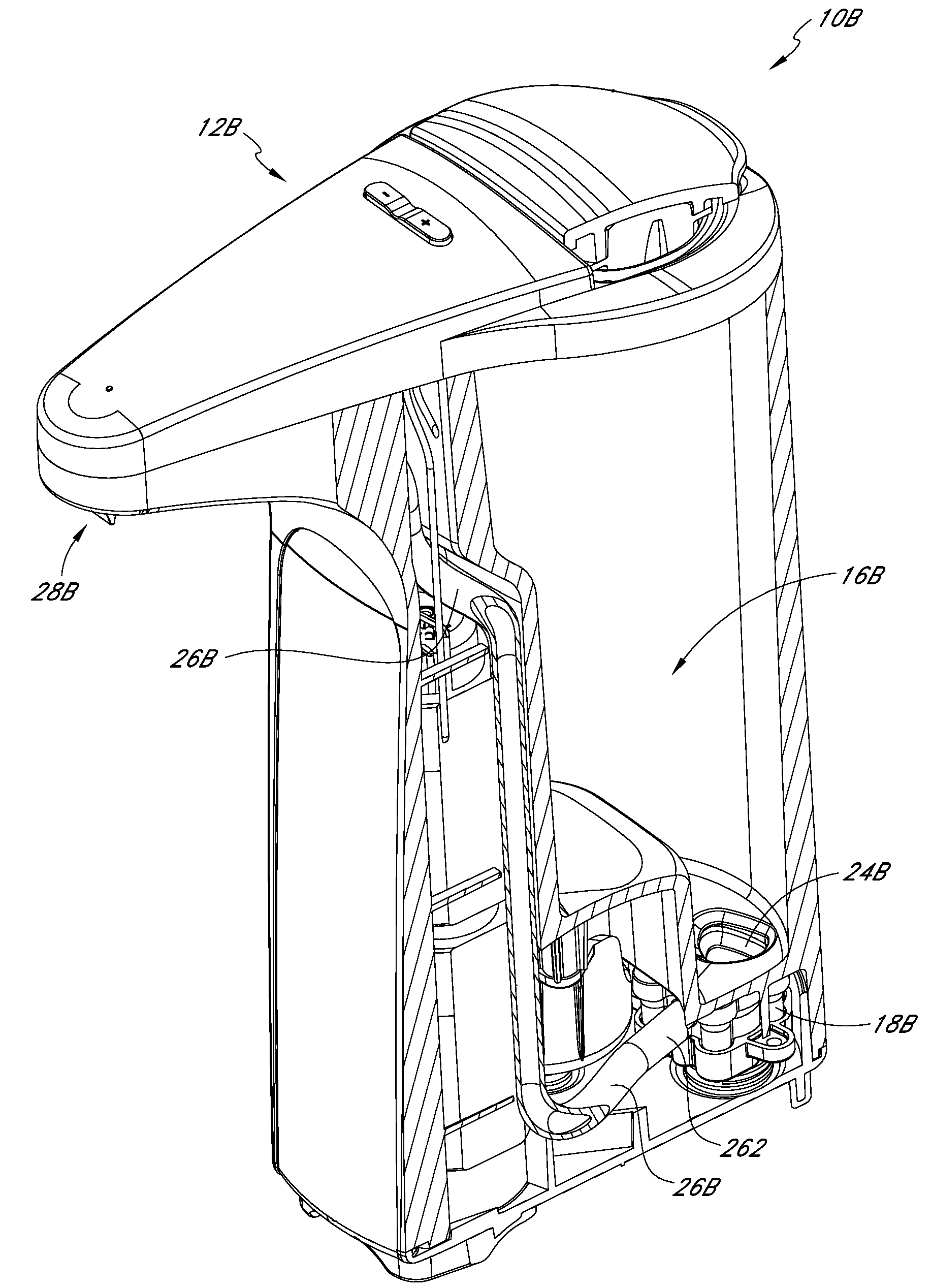
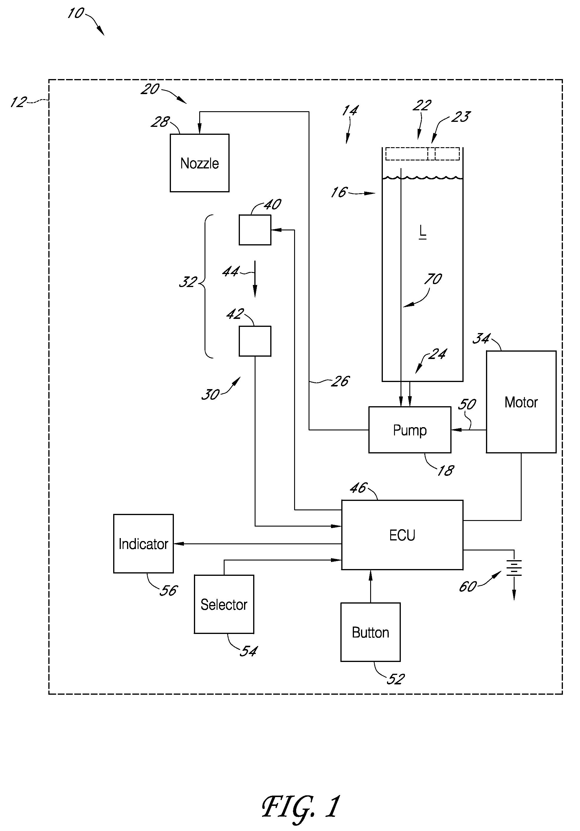
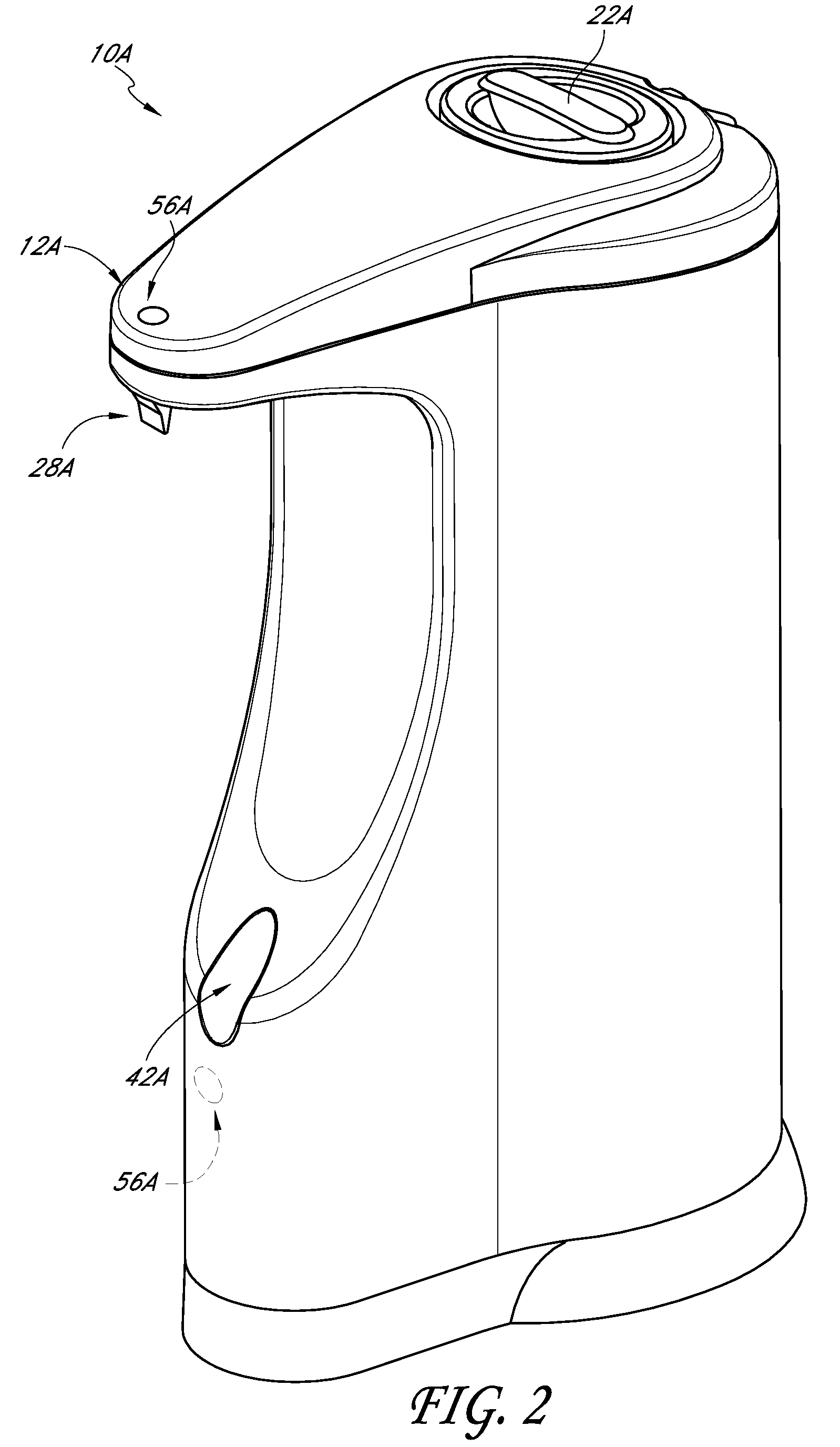
[0068]With reference to FIG. 1, a liquid soap dispenser 10 can include a housing 12, which can take any shape. The dispenser 10 can also include a liquid handling system 14. The liquid handling system 14 can include a reservoir 16, a pump 18, and a discharge assembly 20.

[0069]The reservoir 16 can be any type of container. In the illustrated embodiment, the reservoir 16 is configured to contain a volume of liquid soap L, such as for hand washing. In some embodimen...


PUM


Abstract

A soap dispenser can be configured to dispense an amount of liquid soap, for example, upon detecting the presence of an object. Certain embodiments of the dispenser include a housing, reservoir, pump, and nozzle. In some embodiments, the dispenser includes a bypass passage, which can facilitate priming of the pump. In certain embodiments, the dispenser is configured to inhibit or avoid the formation of an air bubble that could obstruct the liquid soap from entering the pump. In some embodiments, the pump includes engaging gears, which can include a plurality of teeth with substantially pointed tips. In certain embodiments, the nozzle comprises a one-way valve, such as a duckbill valve. Some embodiments of the one-way valve are shaped or otherwise configured to provide certain biases to the valve, which can, for example, facilitate rapid opening and closing of the valve.

Description

CROSS-REFERENCE TO RELATED APPLICATIONS[0001]This application claims the priority benefit under 35 U.S.C. §119(e) of U.S. Provisional Patent Application No. 61 / 449,588, filed Mar. 4, 2011, and U.S. Provisional Patent Application No. 61 / 594,960, filed Feb. 3, 2012, the entirety of each of which is incorporated herein by reference.BACKGROUND[0002]1. Field[0003]The present disclosure relates to soap dispensers, and more particularly, some embodiments relate to soap dispensers with anti-drip valves.[0004]2. Description of the Related Art[0005]Users of modern public washroom facilities increasingly desire that each of the fixtures in the washroom operate automatically without being touched by the user's hand. This is important in view of increased user awareness of the degree to which germs and bacteria may be transmitted from one person to another in a public washroom environment. Today, it is not uncommon to find public washrooms with automatic, hands-free operated toilet and urinal un...

Claims


Application Information

Patent Timeline
Patent Type & Authority Patents(United States)
IPC IPC(8): B65D88/54
CPCB05B9/0866A47K5/1202B05B9/0861B05B12/122A47K5/1217
Inventor YANG, FRANKWOLBERT, DAVIDSANDOR, JOSEPHCARDENAS, ORLANDO
Owner SIMPLEHUMAN
Why Eureka
Try Eureka