Method for directional digital data transmission between an aircraft and a ground station

a digital data and aircraft technology, applied in the field of aircraft-to-ground communication, can solve the problems of single antenna disadvantageous aerodynamically, reduced spectral efficiency of the entire communication system, and prone to thermal noise, and achieves the effect of simple mechanisms and algorithms

Active Publication Date: 2014-07-22
AIRBUS OPERATIONS GMBH
View PDF26 Cites 10 Cited by
  • Summary
  • Abstract
  • Description
  • Claims
  • Application Information

AI Technical Summary

Benefits of technology

[0020]In this arrangement, with this optimized direct digital ground-to-air communication system the entire aircraft communication, including both passenger communication and cockpit communication, can be transmitted digitally and directly to the ground, without having to resort to a satellite.
[0072]The feature whereby, apart from digital data transmission between the aircraft and the ground station, the data transmission always takes place in a directional and direct manner, which can significantly increase the capacity in the allocated spectrum, may be considered a key aspect of the invention. In this manner improved supply of data to the aircraft can be provided. Likewise it is possible to reduce user fees as compared to user fees associated with present-day satellite-bound data transmission. It may be considered a further key aspect of the present invention that emission in the directional antennae of the aircraft takes place in such a manner that only those ground regions are illuminated or beamed at that with regard to the flight path of the aircraft comprise a low change-of-angle speed and a small Doppler frequency offset. Apart from this the invention is in a position, by means of a handover process, to provide continuous data transmission for the aircraft by means of a plurality of ground stations. In this manner it may be possible to reduce the required transmission output of the respective antennae, which apart from a lower electromagnetic radiation load can result in a reduction in the power requirements in the airplane.

Problems solved by technology

This interference can result in a considerable reduction in the spectral efficiency of the entire communication system.
Purely analog signal transmission methods are, as a rule, prone to outside interferences which are, for example, caused by extraneous systems, or are prone to thermal noise that is inherent in any transmission system.
Such an arrangement with a single antenna is disadvantageous aerodynamically as well in respect of the transmitting and receiving characteristics.

Method used


Image

  • Method for directional digital data transmission between an aircraft and a ground station
  • Method for directional digital data transmission between an aircraft and a ground station
  • Method for directional digital data transmission between an aircraft and a ground station

Examples


Embodiment Construction

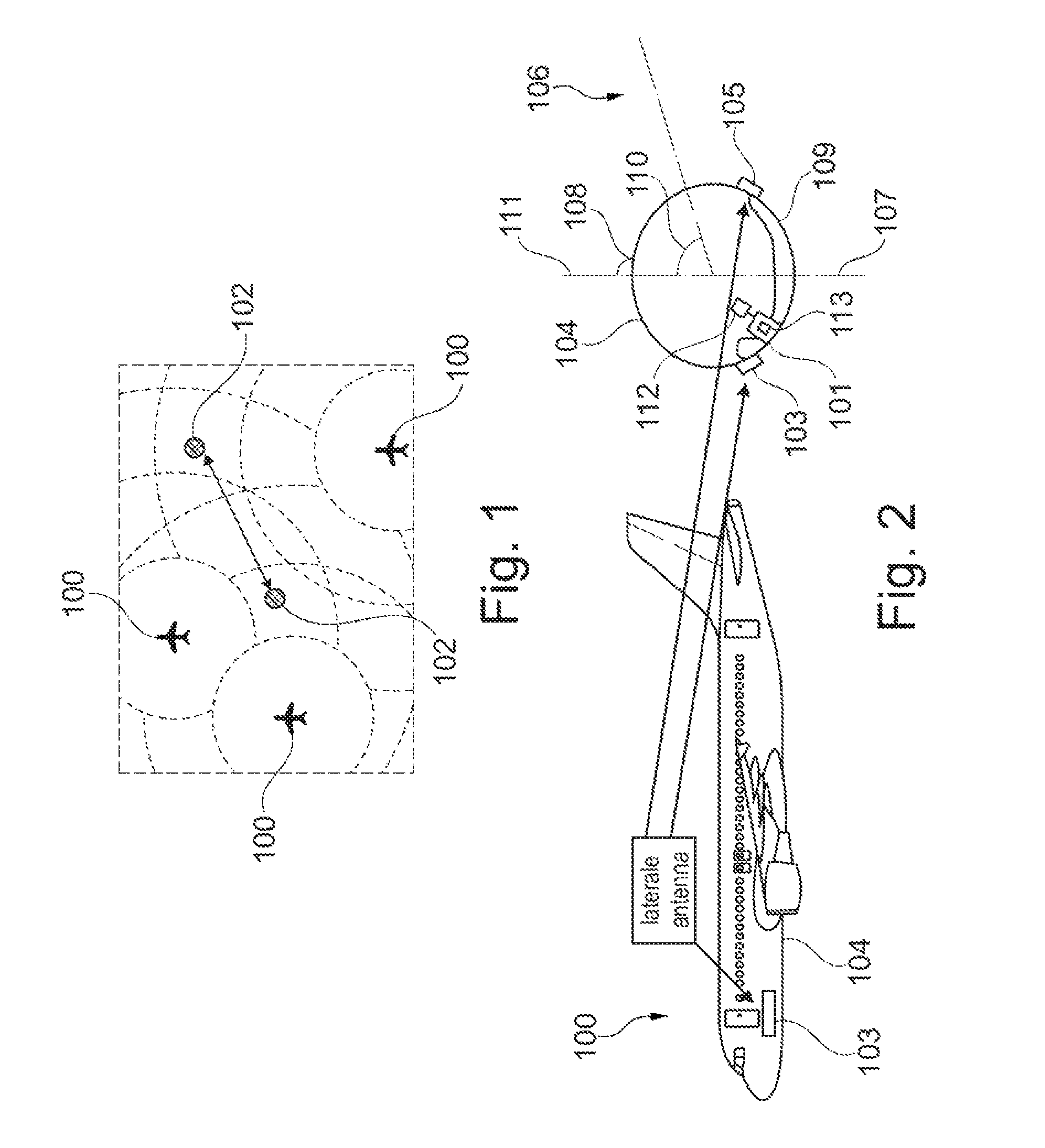
[0086]FIG. 1 shows an example from the state of the art in which by means of isotropic emitters analog data is transmitted from airplanes 100 to ground stations 102.

[0087]FIG. 2 shows an embodiment of the present invention. In this arrangement an aircraft is shown which is designed as an airplane 100 and which laterally or on the side of the fuselage 104 comprises a first directional antenna 103. In this arrangement the right-hand part of FIG. 2 shows a cross section of the fuselage 104, with the illustration showing that on the aircraft fuselage the first antenna 103 and the second antenna 105 are arranged in mirror symmetry relative to the mirror axis 107 in the middle of the fuselage, which antennae 103, 105 are designed as directional antennae.

[0088]Also shown are the skywards facing region 108 of the fuselage, and the region 109 of the fuselage facing the ground. Furthermore, the angle “α”110 is shown. The surface normal 111 of the region 108 facing the sky is also shown in FIG...


PUM


Abstract

The invention relates to a method for digital and directional data transmission between aircraft and ground stations. In this arrangement data is exchanged digitally and directly, in other words directly by means of directional antennae, between the aircraft and the ground stations. Furthermore, transmission lobes are adapted during flight, and the directional antennae on the aircraft only illuminate regions on the ground that are located at a minimum distance across the flight path of the aircraft.

Description

CROSS-REFERENCE TO RELATED APPLICATIONS[0001]This application is a continuation of International Application No. PCT / EP2010 / 056109, filed May 5, 2010, which claims the benefit of the filing date of German Patent Application No. 10 2009 019 995.0, filed on May 5, 2009 and of U.S. provisional patent application No. 61 / 175,553, filed on May 5, 2009, the entire disclosures of which are hereby incorporated herein by reference.FIELD OF THE INVENTION[0002]The invention relates to the communication of aircraft with the ground. In particular, the invention relates to a method for directional digital data transmission between an aircraft and at least one first ground station, to an aircraft comprising a digital transmitter unit for directional digital data transmission between an aircraft and a ground station, and to a communication system for directional digital data transmission between an aircraft and a ground station.TECHNOLOGICAL BACKGROUND[0003]In the communication systems presently in ...

Claims


Application Information

Patent Timeline
Patent Type & Authority Patents(United States)
IPC IPC(8): H04B7/185H01Q1/28H04B7/04
CPCH04B7/18506H04B7/04H01Q1/286H01Q1/28
Inventor FUSS, TIMSCHWARK, UWE
Owner AIRBUS OPERATIONS GMBH
Why Eureka
Try Eureka