Unlock instant, AI-driven research and patent intelligence for your innovation.
Fixing toner using heating-liquid-blocking barrier
What is Al technical title?
Al technical title is built by PatSnap Al team. It summarizes the technical point description of the patent document.
a technology of heating liquid and fixing toner, which is applied in the direction of electrographic process apparatus, instruments, optics, etc., can solve the problems of reducing the heat transfer efficiency of air, slowing down the fixing process, and limiting the heat transfer ability, so as to reduce the probability of blistering, deformation, and other faults, and achieve the effect of effective fixing toner on the receiver medium
Inactive Publication Date: 2015-01-20
EASTMAN KODAK CO
View PDF39 Cites 0 Cited by
Summary
Abstract
Description
Claims
Application Information
AI Technical Summary
This helps you quickly interpret patents by identifying the three key elements:
Problems solved by technology
Method used
Benefits of technology
[0014]An advantage of the present invention is that it effectively fixes toner on a receiver medium. Using a heating liquid provides an effective rate of heat transfer to the toner, and reduces the probability of blistering, deformation, and other faults that can occur while fixing toner on a receiver constrained in its motion (e.g., in a nip). Various aspects are useful for conventional electrophotographic printing. Various aspects provide reduced probability of image damage during fixing. Various aspects use reduced quantities of heating liquid, permitting energy savings. Various aspects heat the opposite side of the receiver medium from a printed image, reducing the probability of image degradation. Various aspects permit controlling the gloss of a printed image without changing the time required to produce that print.
is that it effectively fixes toner on a receiver medium. Using a heating liquid provides an effective rate of heat transfer to the toner, and reduces the probability of blistering, deformation, and other faults that can occur while fixing toner on a receiver constrained in its motion (e.g., in a nip). Various aspects are useful for conventional electrophotographic printing. Various aspects provide reduced probability of image damage during fixing. Various aspects use reduced quantities of heating liquid, permitting energy savings. Various aspects heat the opposite side of the receiver medium from a printed image, reducing the probability of image degradation. Various aspects permit controlling the gloss of a printed image without changing the time required to produce that print.
Problems solved by technology
However, air has a low heat capacity, which limits its ability to transfer heat.
This failure to concentrate the applied heat can slow down the fixing process.
Accordingly, it may not be possible to fix the toner without also heating the receiver.
However, these devices can be slow.
Moreover, contact fixers, e.g., those that pass marked receivers through a fixing nip with a heated roller, can boil or otherwise vaporize moisture in the receiver during fixing.
This can result in blister formation in the receiver and other image defects.
Furthermore, the heated roller on some fixers has a high thermal mass, making it more difficult to change the roller temperature to adjust for variations in fixing characteristics between pages.
Sporer teaches that only that portion of the droplet that has not penetrated or feathered into the paper is available for attracting dry ink, so this process is unsuitable for highly-absorbent papers such as newsprint.
Moreover, Sporer's process does not remove moisture from the receiver, so blistering can still result.
Also, this process is a hybrid of inkjet and powder printing, so is not suitable for use in conventional electrophotographic printers.
Method used
Image
Click on the blue label to locate the original text in one second.
Reading with bidirectional positioning of images and text.
Examples
Embodiment Construction
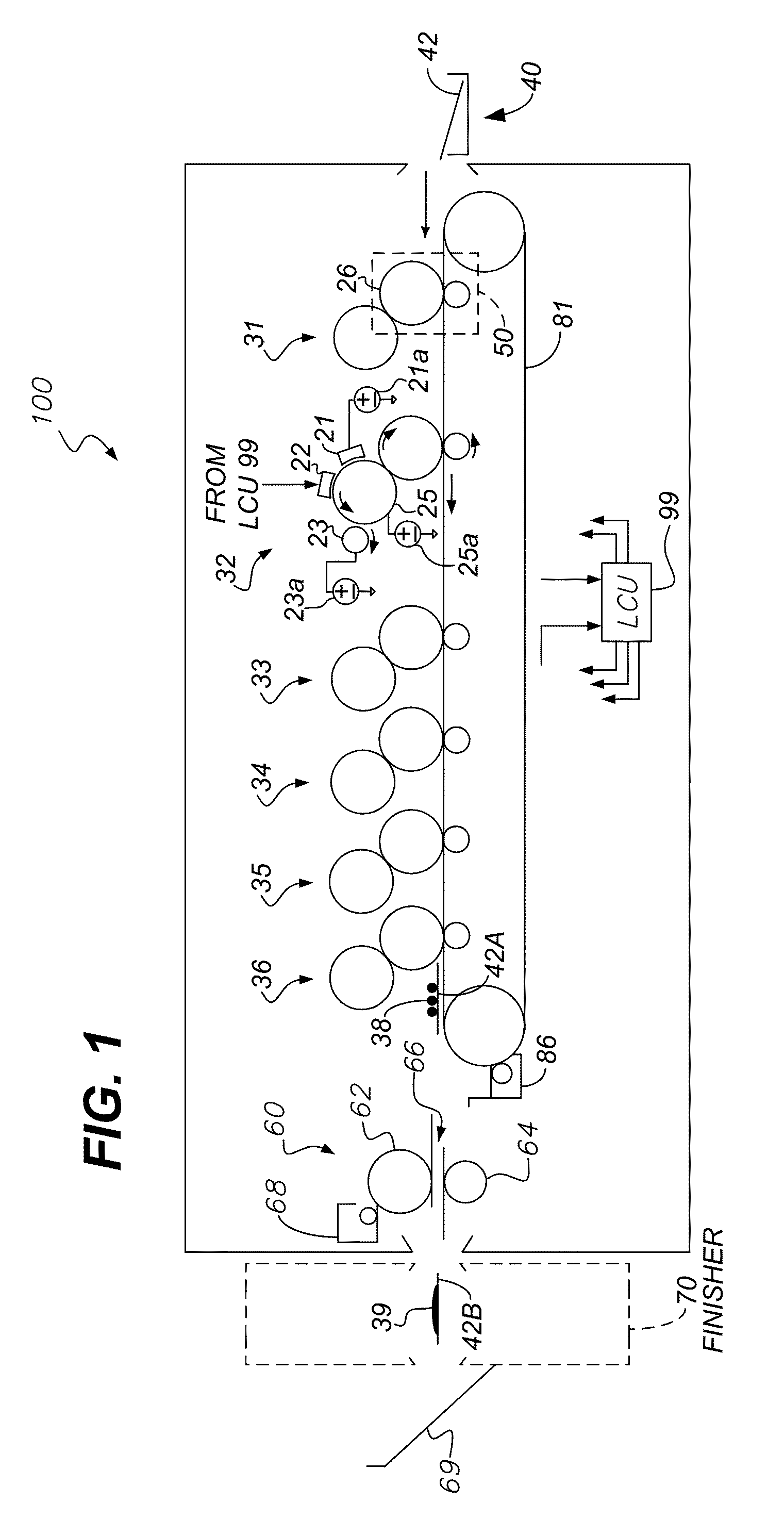
[0026]Electrophotographic (EP) and other toner printing processes can be embodied in devices including printers, copiers, scanners, and facsimiles, and analog or digital devices, all of which are referred to herein as “printers.” A digital reproduction printing system (“printer”) typically includes a digital front-end processor (DFE), a print engine (also referred to in the art as a “marking engine”) for applying toner to the recording medium, and one or more post-printing finishing system(s) (e.g., a UV coating system, a glosser system, or a laminator system). A printer can reproduce pleasing black-and-white or color visible images onto a recording medium. A printer can also produce selected patterns of toner on a recording medium, which patterns (e.g., surface textures) do not correspond directly to a visible image. The DFE receives input electronic files (such as Postscript command files) composed of images from other input devices (e.g., a scanner, or a digital camera). The DFE ...
PUM
Abstract
A method for fixing toner onto a receiver medium includes depositing a pattern of toner onto a surface of the receiver medium. A liquid-blocking barrier is provided that has a first surface and a second surface that is impermeable to a heating liquid. The surface of the receiver medium is brought into contact with the first surface of the liquid-blocking barrier. The heating liquid is brought into contact with the second surface of the liquid-blocking barrier. The heating liquid is at a temperature greater than the toner glass transition temperature. Heat is transferred through the liquid-blocking barrier from the heating liquid to the toner, thereby raising the temperature of the toner to a temperature above the toner glass transition temperature.
Description
CROSS-REFERENCE TO RELATED APPLICATIONS[0001]Reference is made to commonly assigned, U.S. patent application Ser. No. 13 / 649,143, now U.S. Pat. No. 8,756,825, entitled: “Removing moistening liquid using heating-liquid barrier”, by Priebe et al.; to commonly assigned, co-pending U.S. patent application Ser. No. 13 / 662,726, entitled “Applying heating liquid to fix toner,” by Priebe et al.; to commonly assigned, co-pending U.S. patent application Ser. No. 13 / 662,752, entitled “Toner fixer transporting medium through heating liquid, by Priebe et al.; to commonly assigned, co-pending U.S. patent application Ser. No. 13 / 662,771, entitled “Toner fixer impinging heating liquid onto medium,] by Priebe et al.; to commonly assigned, co-pending U.S. patent application Ser. No. 13 / 662,798, entitled “Transported medium heating-liquid-barrier toner fixer,” by Priebe et al.; to commonly assigned, co-pending U.S. patent application Ser. No. 13 / 662,811, entitled “Toner-fixing drum containing heating ...
Claims
Application Information
Patent Timeline
Application Date:The date an application was filed.
Publication Date:The date a patent or application was officially published.
First Publication Date:The earliest publication date of a patent with the same application number.
Issue Date:Publication date of the patent grant document.
PCT Entry Date:The Entry date of PCT National Phase.
Estimated Expiry Date:The statutory expiry date of a patent right according to the Patent Law, and it is the longest term of protection that the patent right can achieve without the termination of the patent right due to other reasons(Term extension factor has been taken into account ).
Invalid Date:Actual expiry date is based on effective date or publication date of legal transaction data of invalid patent.
Patent Type & Authority Patents(United States)
IPC IPC(8): G03G15/20
CPCG03G15/2096
Inventor PRIEBE, ALAN RICHARDRIMAI, DONALD SAULWHITE, CHRISTOPHER J.SPAULDING, KEVIN EDWARD