Vehicle seat

a technology for vehicles and seats, applied in vehicle parts, vehicle arrangements, domestic applications, etc., can solve the problems of low efficiency of the work of attaching the reinforcement member, and achieve the effect of high work efficiency, and high handleability of the operation portion

Inactive Publication Date: 2015-02-24
TOYOTA BOSHOKU KK
View PDF52 Cites 8 Cited by
  • Summary
  • Abstract
  • Description
  • Claims
  • Application Information

AI Technical Summary

Benefits of technology

[0007]The invention provides a vehicle seat that achieves a high handleability of an operation portion by attaching a reinforcement member such that an outer shield does not break and does not fall off from a cushion frame even when the recliner is unlocked by pulling the operation portion obliquely rearward from the rear seat side, and also achieves a high efficiency of work for attaching the reinforcement member.
[0008]The first aspect of the invention relates to a vehicle seat having: a recliner that adjusts an inclination angle of a seatback assembly relative to a seat cushion assembly; an outer shield that covers a side face of a cushion frame of the seat cushion assembly; an operation portion that protrudes toward a rear seat from an opening formed at the outer shield and that is used to unlock the recliner from the rear seat side; and a reinforcement member that is attached to the cushion frame so as to cover a notch formed near the opening of the outer shield. In this vehicle seat, an engagement hook that engages with an engagement hole formed at an edge of the notch and a fixing portion that is fixed to a plate provided at the cushion frame are formed at the reinforcement member. According to the vehicle seat structured as described above, as in the structure described in Japanese Patent Application Publication No. 2010-228614, even when the recliner is unlocked by pulling the operation portion obliquely rearward, the outer shield does not break and does not fall off from the cushion frame, and therefore the handleability of the operation portion is high. According to the vehicle seat structured as described above, further, unlike the structure described in Japanese Patent Application Publication No. 2010-228614, since the reinforcement member is attached using the engagement hook, the reinforcement member can be easily attached, improving the efficiency of the work for attaching the reinforcement member.
[0009]The vehicle seat of the first aspect of the invention may be such that the fixing portion is an insert groove into which the plate is inserted so as to be sandwiched by the insert groove in a lateral direction of the vehicle seat as the engagement hook of the reinforcement member is engaged with the engagement hole. According to this structure, since the fixing portion is the insert groove into which the plate is inserted so as to be sandwiched by the insert groove in the lateral direction of the vehicle seat as the engagement hook of the reinforcement member is engaged with the engagement hole, it is not necessary to perform a work for attaching the reinforcement member and a work for fixing the reinforcement member to the plate separately. As such, the work efficiency is high.
[0010]The vehicle seat described above may be such that the reinforcement member has an engagement piece facing the engagement hook of the reinforcement member and the engagement hook of the reinforcement member is engaged with the engagement hole by being rotated, relative to the outer shield, about the engagement piece of the reinforcement member. According to this structure, for example, since the reinforcement member can be attached with one hand, the efficiency of the work for attaching, the reinforcement member is even higher.

Problems solved by technology

According to the structure described in Japanese Patent Application Publication No. 2010-228614, however, since the reinforcement member is fixed to the cushion frame side using screws, the efficiency of the work for attaching the reinforcement member is low.

Method used


Image

  • Vehicle seat
  • Vehicle seat
  • Vehicle seat

Examples


Embodiment Construction

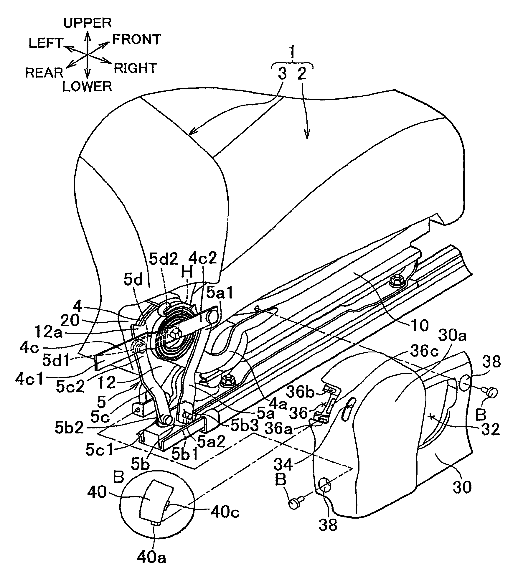
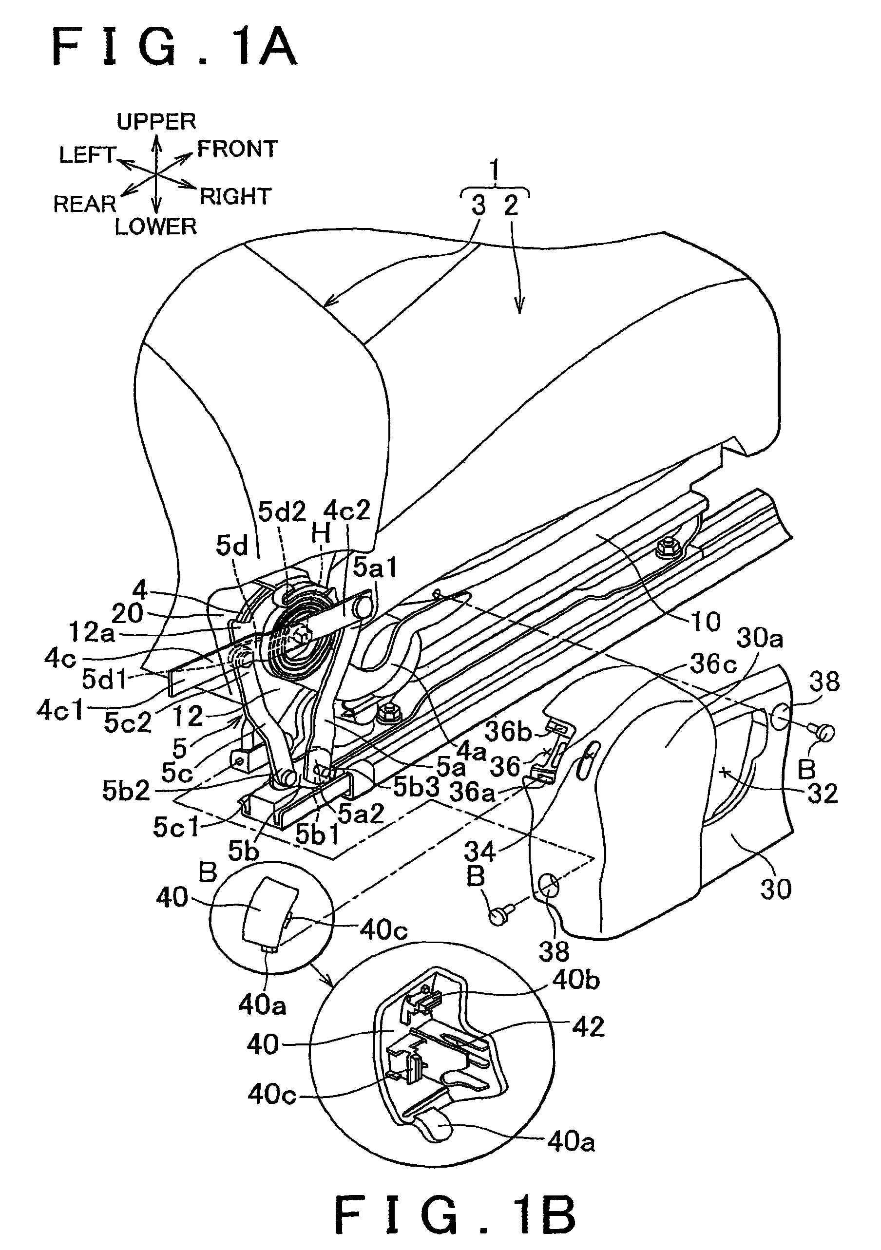
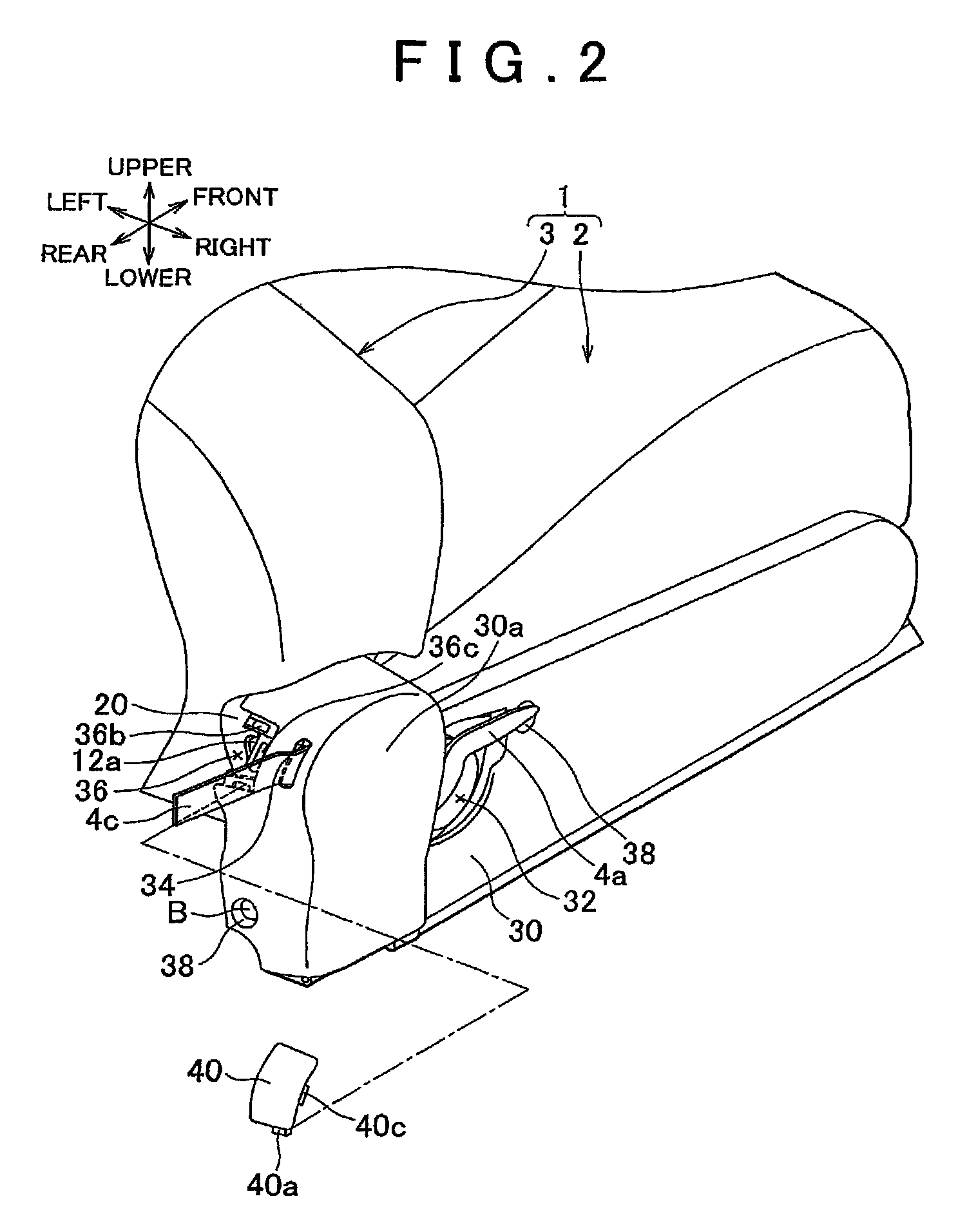
[0019]Hereinafter, an example embodiment of the invention will be described with reference to FIGS. 1 to 6. In the following, a first row seat 1 (e.g., a driver's seat) will be described as an example of “vehicle seat”. Further, although not shown in the drawings, a second row seat is present behind, the first row seat 1. It is to be noted that “upper”, “lower”, “front”, “rear”, “left”, and “right” in the following descriptions shall be interpreted as corresponding, respectively, to the upper side, lower side, front side, rear side, left side, and right side as viewed in the drawings, that is, the upper side, lower side, front side, rear side, left side, and right side of the first row seat 1.

[0020]First, the outline of the structure of a first row seat 1 of the example embodiment of the invention will be described with reference to FIGS. 1 and 2. The first row seat 1 is constituted of a seat cushion assembly 2 and a seatback assembly 3 that are connected to each other via recliners...


PUM


Abstract

A vehicle seat is provided with an operation portion that protrudes toward a rear seat from an opening formed at an outer shield and that is used to unlock a recliner from the rear seat side and a reinforcement member that is attached to a cushion frame side so as to cover a notch formed near the opening of the outer shield. Engagement hooks that engage with respective engagement holes formed at edges of the notch and a fixing portion that is fixed to a plate provided at the cushion frame side are formed at the reinforcement member.

Description

INCORPORATION BY REFERENCE[0001]The disclosure of Japanese Patent Application No. 2011-030975 filed on Feb. 16, 2011 including the specification, drawings and abstract is incorporated herein by reference in its entirety.BACKGROUND OF THE INVENTION[0002]1. Field of the Invention[0003]The invention relates to a vehicle seat, and more specifically it relates to a vehicle seat of which a recliner can be unlocked by pulling an operation portion, protruding toward a rear seat side from an opening formed at an outer shield, rearward from the rear seat side.[0004]2. Description of Related Art[0005]A vehicle seat is known which has a recliner that can be unlocked by pulling an operation portion (strap), protruding toward a rear seat side from an opening formed at an outer shield, rearward from the rear seat side. Japanese Patent Application Publication No. 2010-228614 describes a vehicle seat in which a reinforcement member (bezel) is provided at an edge of an opening of an outer shield. Acc...

Claims


Application Information

Patent Timeline
Patent Type & Authority Patents(United States)
IPC IPC(8): A47B97/00B60N2/90B60N2/22B60N2/60
CPCB60N2/6009B60N2/22
Inventor MITA, HIROYUKIUEDA, JUN
Owner TOYOTA BOSHOKU KK
Why Eureka
Try Eureka