Abnormal voltage detecting device

a voltage detection and abnormal technology, applied in the direction of instruments, two-wire dc circuits, arrangements responsive to excess voltage, etc., can solve the problems of complicated construction, disturbance of the start-up time and the monitoring voltage vb>1/b> of the voltage generating apparatus is not very fast in the startup period of the apparatus, so as to achieve a substantially simplified circuit construction and facilitate production

Active Publication Date: 2015-07-28
FUJI ELECTRIC CO LTD
View PDF7 Cites 2 Cited by
  • Summary
  • Abstract
  • Description
  • Claims
  • Application Information

AI Technical Summary

Benefits of technology

[0014]The present invention has been accomplished in view of the situation described above and an object of the invention is to provide an abnormal voltage detecting device with a simple construction that avoids erroneous detection of abnormal voltage decrease in the start up period of a voltage generating apparatus while monitoring the abnormal decrease in the output voltage of the voltage generating apparatus in the start up period of the apparatus.
[0023]Therefore, on starting up a voltage generating apparatus, the voltage generating apparatus is allowed to be monitored for abnormal decrease in an output voltage of the apparatus only excepting the initial start up period in the start up procedure. The monitoring for abnormal decrease of the monitoring voltage V1 in the invention is conducted using the reference voltage Vss1 for a start up period that is obtained by reducing, in a predetermined amount, voltage from the reference voltage Vss for soft starting as a threshold value for determining an abnormality. Therefore, any erroneous detection of abnormal decrease in the output voltage is more effectively avoided in the procedure of start up of a voltage generating apparatus as compared with a monitoring method that uses, for example, the reference voltage Vss for soft starting as a threshold value for determining abnormality.
[0024]The abnormal voltage detection device utilizes the three input comparator effectively to compare the monitoring voltage V1 with the reference voltage Vref, and the reference voltage Vss1 for a start up period. The reference voltage Vss1 for a start up period is simultaneously utilized for controlling inhibition of operation of the output circuit. As a consequence, the circuit construction is substantially simplified as compared with the conventional construction comprising two comparators for separately detecting and determining abnormality of the monitoring voltage V1 and the reference voltage Vss for soft starting, and additional gate circuitry for output control of the abnormality detecting signal Vout. The simplified construction can be readily produced in an integrated circuit structure.

Problems solved by technology

However, the rise up of the monitoring voltage V1 of the voltage generating apparatus is not very fast in the startup period of the apparatus.
As a consequence, the start up itself of the voltage generating apparatus may be disturbed.
However, in order to detect abnormal decrease in the output voltage while monitoring start of the voltage generating apparatus using the reference voltage Vss for soft starting, an abnormal voltage detecting circuit of the voltage generating apparatus needs the two comparators CP1 and CP2 as described above and thus results in a complicated construction.
In addition, since the above-described conventional construction renders the monitoring of the abnormal decrease in the output voltage inactive in the start up period of the voltage generating apparatus, it is impossible to know whether the voltage generating apparatus is working normally or not, which is another problem in the conventional technology.

Method used


Image

  • Abnormal voltage detecting device
  • Abnormal voltage detecting device
  • Abnormal voltage detecting device

Examples


Embodiment Construction

[0030]The following describes an abnormal voltage detecting device according to an embodiment of the present invention with reference to the accompanying drawings.

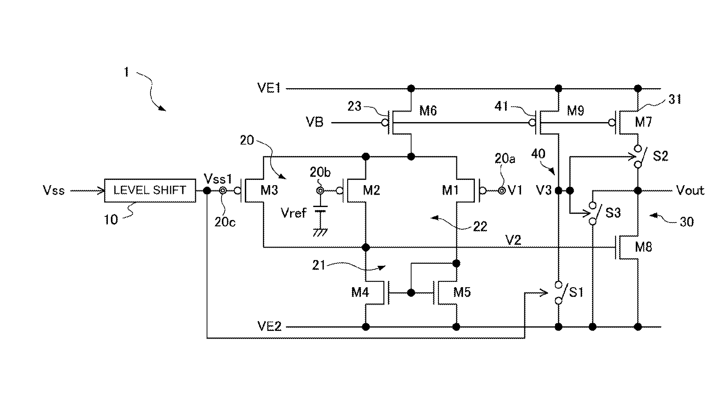
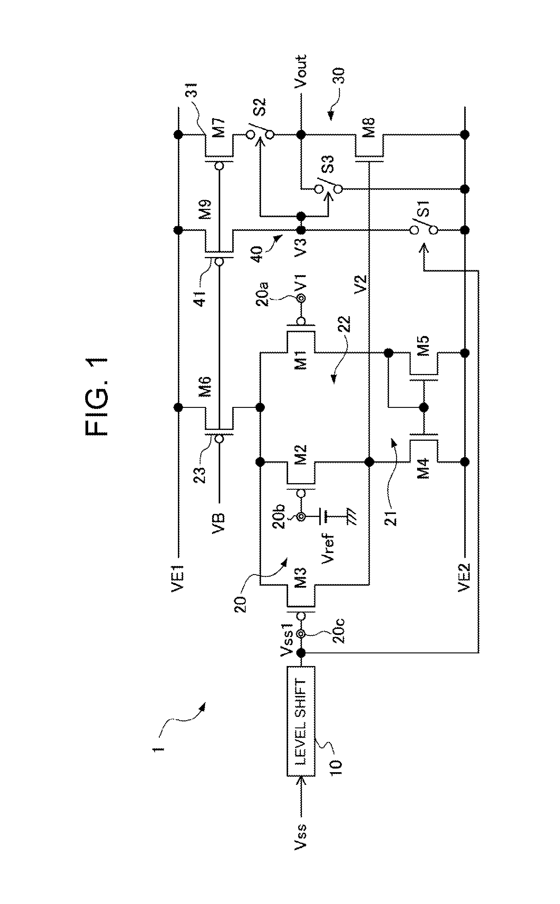
[0031]This abnormal voltage detecting device monitors a monitoring voltage V1 detected by, for example, resistor-dividing the output voltage generated by a voltage generating apparatus (not shown in the figure). Upon detecting abnormal decrease in the monitoring voltage V1, the abnormal voltage detecting device delivers an abnormality detecting signal Vout to operate a low voltage protection circuit (not shown in the figure) of the voltage generating apparatus thereby interrupting voltage delivery of the voltage generating apparatus.

[0032]FIG. 1 shows a schematic construction of an abnormal voltage detecting device according to an embodiment of the present invention. A level shift circuit 10 generates a reference voltage Vss1 for a start up period by level-shifting, or reducing, by a predetermined amount of voltage, a refe...


PUM


Abstract

An abnormal voltage detecting device monitors abnormal decrease in monitoring voltage during a start up period of a voltage generating apparatus. The abnormal voltage detecting device comprises a level shift circuit that generates a reference voltage for a start up period by reducing, in a predetermined amount, voltage from a reference voltage for soft starting, and further comprises a three input comparator that receives a monitoring voltage, a reference voltage Vref, and the reference voltage for the start up period, and that reverses a logical output when the monitoring voltage is lower than the reference voltage Vref and the reference voltage for the start up period. An abnormality detecting signal is delivered when the logical output of the three input comparator is reversed, and operation of an output circuit is inhibited until the reference voltage for the start up period exceeds a predetermined start up determining voltage.

Description

CROSS-REFERENCE TO RELATED APPLICATION[0001]This application is based on, and claims priority to, Japanese Patent Application No. 2012-139238, filed on Jun. 20, 2012, contents of which are incorporated herein by reference.BACKGROUND OF THE INVENTION[0002]1. Field of the Invention[0003]The present invention relates to voltage monitoring technology for detecting decrease in the monitoring voltage and operating a protection circuit, and in particular, to an abnormal voltage detecting device capable of avoiding erroneous detection in a start up period of a voltage generating apparatus.[0004]2. Description of the Related Art[0005]Voltage generating apparatuses, typically power supply circuits and reference voltage generating circuits, are provided with a low voltage protection circuit for interrupting voltage output from the voltage generating apparatus when the output voltage has decreased below a predetermined lower limit voltage, as described in Patent Documents 1 and 2 (identified be...

Claims


Application Information

Patent Timeline
Patent Type & Authority Patents(United States)
IPC IPC(8): H02H3/00H02H3/24G01R19/165G01R19/00H02J1/06H02H3/10H02H3/20
CPCH02H3/24G01R19/16576G01R19/0084H02H3/105H02H3/207H02J1/06
Inventor SUGAHARA, SATOSHI
Owner FUJI ELECTRIC CO LTD
Why Eureka
Try Eureka