Supercharge Your Innovation With Domain-Expert AI Agents!

Printing method and printing device for fabrics

a printing device and fabric technology, applied in printing presses, typewriters, printing, etc., can solve the problems of printing device description, inability to perform printing with high precision, damage to the printing medium, etc., to achieve the effect of preventing the change of tensile force value significantly, and high precision

Active Publication Date: 2015-09-08
ROLAND DG CORP
View PDF12 Cites 0 Cited by
  • Summary
  • Abstract
  • Description
  • Claims
  • Application Information

AI Technical Summary

Benefits of technology

[0014]Preferred embodiments of the present invention provide a printing method and a printing device usable for fabrics that are capable of performing printing with high precision without the printing position being deviated much or significantly.
[0018]According to a preferred embodiment of the present invention, the feed roll is rotated by the first motor, and thus the fabric material is fed downstream. The rotation amount of the feed roll is controlled, and thus the feed operation on the fabric material is performed at a position below the print head. Along with the feed operation on the fabric material, the supply / feed roll located upstream with respect to the position below the print head is also driven by the second motor. At a position upstream with respect to the position below the print head, the fabric material is actively fed. Therefore, the tensile force of the fabric material is prevented from being changed at the position below the print head due to the fabric material being pulled by the feed roll.
[0019]According to a preferred embodiment of the present invention, the tensile force of the fabric material is detected at a position upstream with respect to the position below the print head. The second motor is controlled based on the detected value of the tensile force and the preset target tensile force value. As a result, the change in the tensile force value is significantly reduced or prevented more effectively. Therefore, according to a preferred embodiment of the present invention, even when the printing medium is an elastic material like the fabric material, the expansion and contraction of such an elastic material, which would otherwise be caused by the change in the tensile force, is significantly reduced or prevented. Therefore, printing at a deviated position, which would otherwise be caused due to the change in the tensile force, is prevented, and thus the printing is performed with high precision.
[0020]The first feed operation is performed intermittently. There are cases where the active feed of the fabric material by the supply / feed roll does not directly lead to the feed of a portion of the fabric material that is at the position below the print head due to, for example, the frictional resistance between the fabric material and the support roll 4. In such a case, in the initial period of the first feed operation, the tensile force of the portion of the fabric material that is located at the position below the print head may be temporarily increased significantly. In a preferred embodiment according to the present invention, in at least the initial period of the first feed operation, the acceleration set to drive the second motor is preferably set to be larger than the acceleration set to drive the first motor. In another preferred embodiment according to the present invention, the time to start driving the second motor is set to be prior to the time to start driving the first motor. As a result of such an arrangement, in the initial period of the first feed operation, the increase in tensile force of the fabric material is prevented.

Problems solved by technology

The printing medium, which is conveyed while being supported by the platen, is, for example, damaged by being rubbed with the platen.
For this reason, the printing device described in Japanese Laid-Open Patent Publication No. 2009-090578 cannot perform printing with high precision when the printing medium is a fabric material.

Method used


Image

  • Printing method and printing device for fabrics
  • Printing method and printing device for fabrics
  • Printing method and printing device for fabrics

Examples


Embodiment Construction

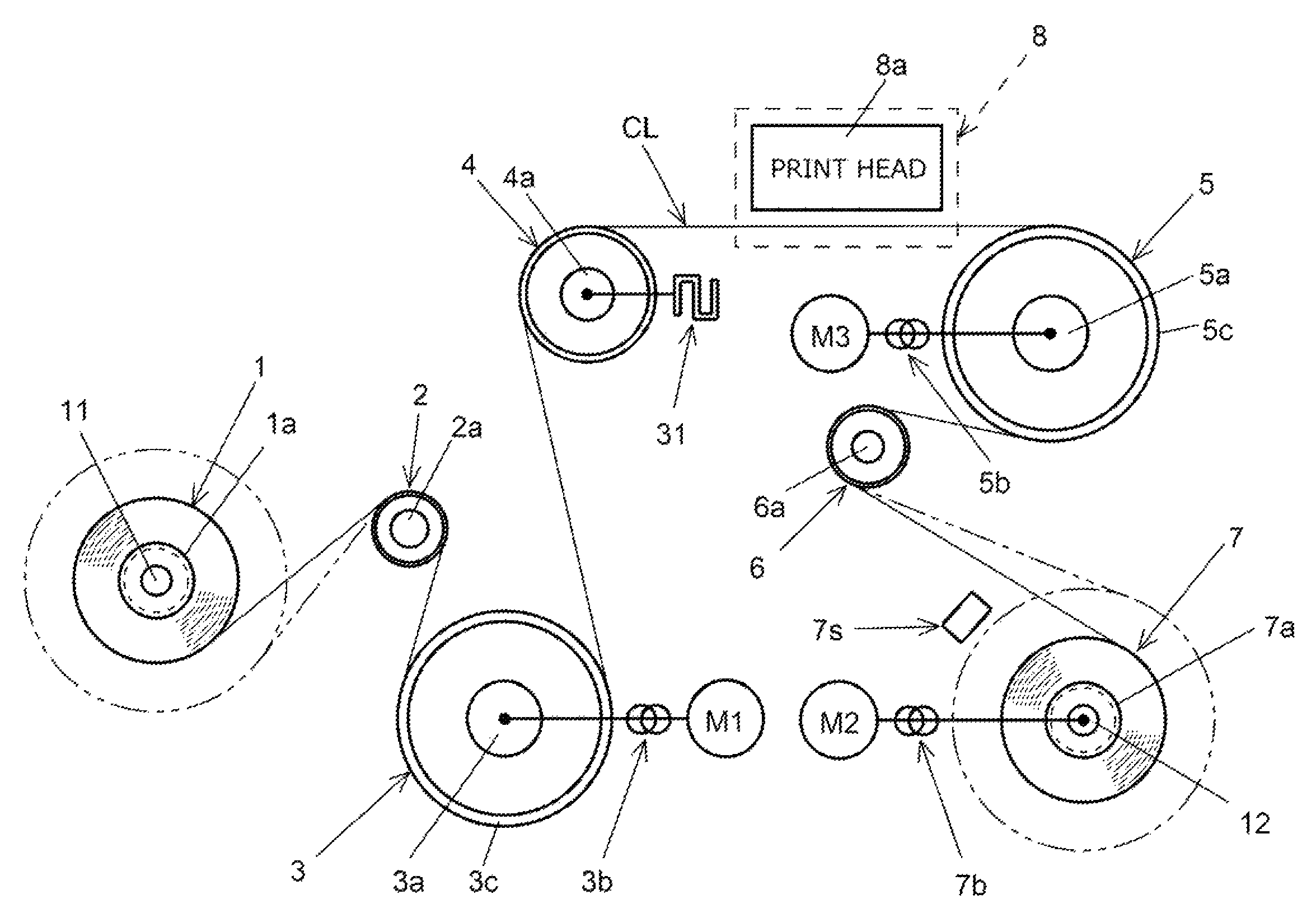
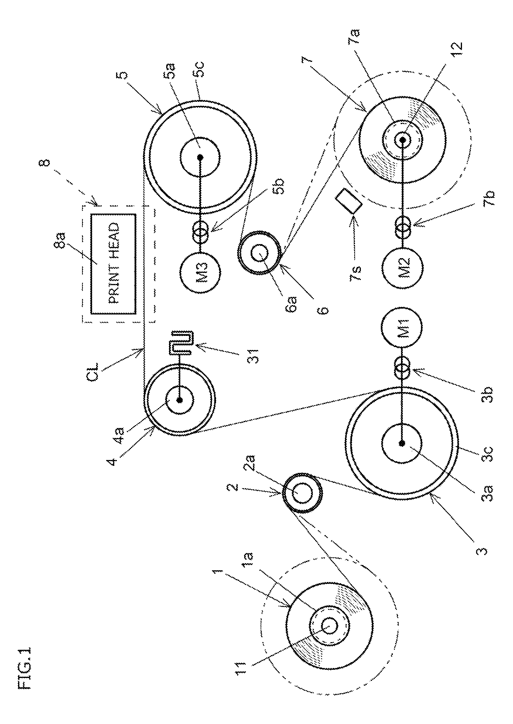
[0031]FIG. 1 through FIG. 5 show a printing device usable for fabrics in a preferred embodiment according to the present invention.

[0032]In the following description, a portion which supplies a fabric material CL toward a print unit 8 will be referred to as a “supply / feed portion”. As shown in FIG. 1, in the supply / feed portion, a serving roll 3 is driven by a motor M1 and thus is rotated. The motor M1 preferably is a servo motor in this preferred embodiment, but there is no specific limitation on the type of the motor M1. The motor M1 is an example of a “second motor”. The fabric material CL is wound around the serving roll 3. When the motor M1 is rotated, the fabric material CL is fed from a supply roll 1 intermittently.

[0033]After passing the print unit 8, the fabric material CL is wound around a feed roll 5. The feed roll 5 is rotated to feed the fabric material CL. Hereinafter, the operation of the feed roll 5 of feeding the fabric material CL will be also referred to simply as...


PUM


Abstract

A printing method is performed by use of a printing device. The printing device includes a print head, a supply roll, a serving roll, a support roll, a feed roll, and a winding roll. The printing device feeds a fabric material toward the winding roll by a prescribed length each time that a cycle of a print operation is performed by the print head, so that the printing is performed on the fabric material intermittently. The printing method includes performing a first feed operation of intermittently rotating the feed roll by a first motor to pull the fabric material from a print unit and feed the fabric material toward the winding roll by a prescribed length; and performing a second feed operation of intermittingly rotating the serving roll by a second motor to feed the fabric material toward the print unit. A detected tensile force value based on a detected value of the tensile force of the fabric material detected at a position upstream with respect to the print unit is compared to a preset target tensile force, and the second motor is controlled based on a result of the comparison.

Description

[0001]The present application claims priority from Japanese Patent Application No. 2013-031075 filed on Feb. 20, 2013, which is incorporated by reference herein in its entirety.BACKGROUND OF THE INVENTION[0002]1. Field of the Invention[0003]The present invention relates to a printing method and a printing device usable for fabrics.[0004]2. Description of the Related Art[0005]A known printing device usable for fabrics includes a supply roll around which a lengthy fabric material as a printing medium is wound, a support roll for winding therearound the fabric material fed from the supply roll and guiding the fabric material to a print unit, a print head which is located to be above the fabric material in the print unit and is provided for performing printing on the fabric material, and a winding roll which is rotatable when being driven and is provided for winding therearound the fabric material which has passed the print unit. In such a printing device, each time that one cycle of a ...

Claims


Application Information

Patent Timeline
Patent Type & Authority Patents(United States)
IPC IPC(8): B41F17/00B41J15/16B41J3/407
CPCB41F17/003B41J3/4078B41J15/16
Inventor HASEGAWA, HIROAKIMATSUYAMA, YUTAKAYAMAMURA, KOJI
Owner ROLAND DG CORP
Features
  • R&D
  • Intellectual Property
  • Life Sciences
  • Materials
  • Tech Scout
  • Unparalleled Data Quality
  • Higher Quality Content
  • 60% Fewer Hallucinations
Learn More