Check patentability & draft patents in minutes with Patsnap Eureka AI!

Method and support apparatus for supporting down hole rotary tools

a rotary tool and support device technology, applied in the direction of drilling rods, drilling pipes, drilling/well accessories, etc., can solve the problems of difficult removal of tubular casings when required, inability to uncouple tubular drill casings in this manner, and large amount of force to raise the tubular to overcome the resisting for

Active Publication Date: 2015-12-22
SWIVEL RENTAL & SUPPLY L L C
View PDF7 Cites 9 Cited by
  • Summary
  • Abstract
  • Description
  • Claims
  • Application Information

AI Technical Summary

Benefits of technology

This solution significantly reduces the time and effort required for casing removal and handling, providing a more efficient and certain method for plug and abandon operations, even in space-constrained offshore environments, by enabling simultaneous drilling and supporting a range of downhole tools and operations.

Problems solved by technology

Often in such cases, the drill bit being used to advance the drilling cannot pass through the previously installed tubular casing due to an obstruction.
The removal of the tubular casing when required is often very difficult due to the tremendous weight of the tubular strings and, in some eases, the cement that has been placed around and between the various tubular strings.
Such lifting devices may be the rig's crane if available and not in use by other drilling operations on the site.
However, in many cases the drill casing tubular cannot be uncoupled in this manner.
As discussed above, raising the tubular requires an extensive amount of force to overcome the resisting forces.
The operators usually drill one side at a time, a slow and tedious process, especially with heavy gauge pipe.
Although the time required to drill the holes may be drastically reduced in such cases, a significant amount of time is still required to set up, and to clear, lubricate, and repair the drill bits.
Such sites have very limited space available and therefore the size of the temporary derrick must be restricted.

Method used


Image

  • Method and support apparatus for supporting down hole rotary tools
  • Method and support apparatus for supporting down hole rotary tools
  • Method and support apparatus for supporting down hole rotary tools

Examples


Embodiment Construction

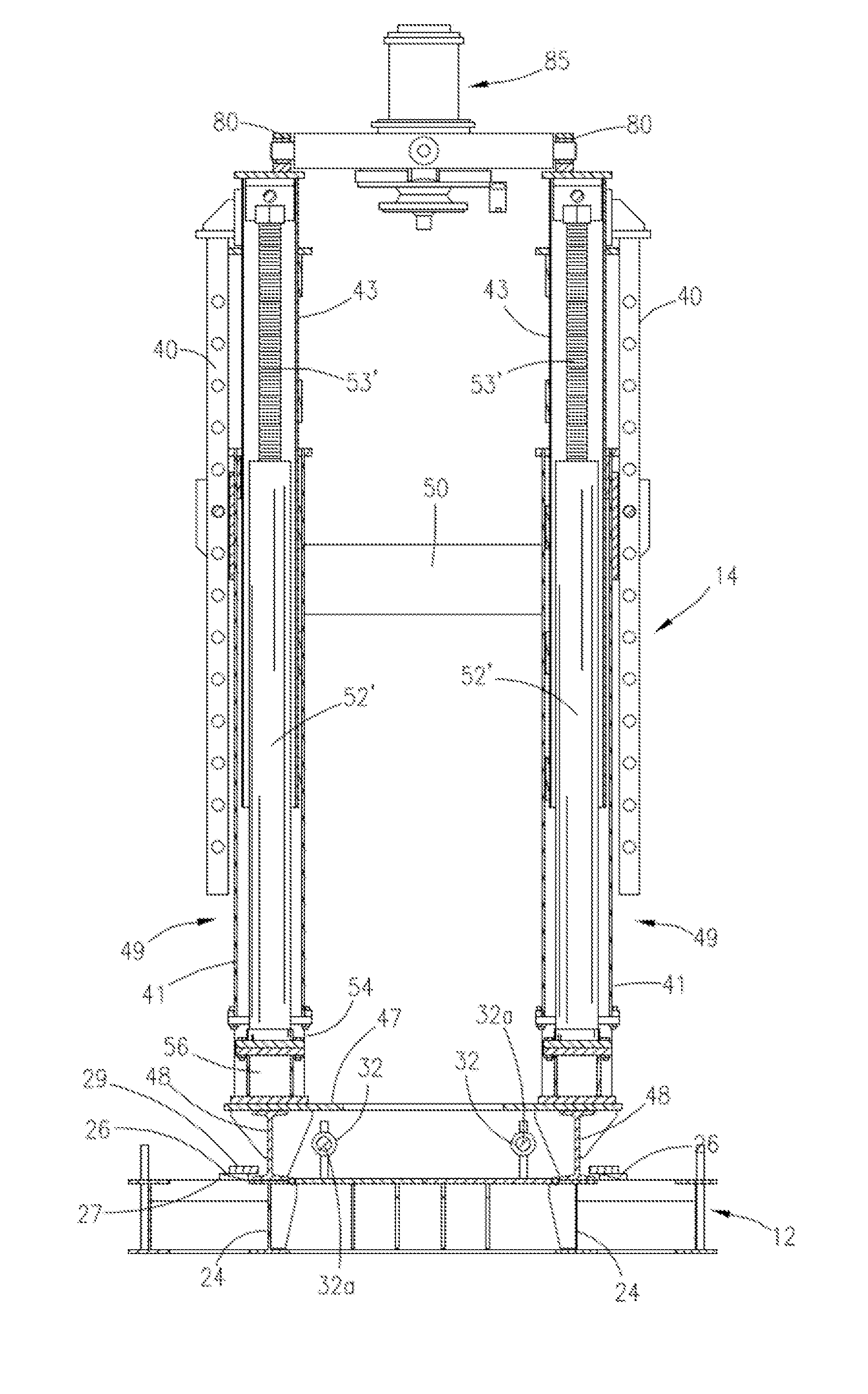
[0032]As first seen in FIG. 1, the frame assembly 10 includes a horizontally oriented skid assembly 12, a vertically oriented, extendable and retractable, mast assembly 14, and a pivotal crane assembly 16 as support for various downhole tools such as optional hydraulic power swivel assembly 11. The mast assembly is slidably positionable on the skid frame. The skid assembly 12 is positioned on the well platform deck 13 adjacent to a platform wellhead opening 15.

[0033]As seen in FIG. 2, the horizontally oriented skid assembly 12 includes a perimeter frame 18, lifting eyes 20, transverse cross members 22, longitudinal support beams 24 that extend longitudinally along the length of the frame, longitudinal guides 26 that correspond to the support beams 24, decking 28 and pivotal deck doors 30. The guide 26 shown is comprised of overlapping stacked plates mounted to the support beams 24. The top surface of each support beam 24 is positioned flush with the decking 28.

[0034]The mast assembl...


PUM


Abstract

A portable frame assembly having a skid assembly for supporting a vertically oriented mast assembly is disclosed. The mast assembly is comprised of at least two column assemblies that may be extended or retracted vertically as desired. The mast assembly is translatable to slide horizontally on the skid assembly without the need for tracks or rollers by means of powered actuators to allow for a desired placement of the mast assembly. The portable frame assembly may be positioned adjacent a wellhead for the purpose of performing plug and abandon operations and may include a power swivel and other such hydraulic or mechanical tools for performing a variety of operations on a well including removing and plugging well casing strings, milling pipe strings, cement drilling, removing wellhead assemblies, or setting and pulling plugs from pipe strings.

Description

[0001]This is a divisional application under 37 CFR 1.53(b) entitled “Method and Support Apparatus for Supporting Down Hole Rotary Tools”. This application claims priority to currently pending U.S. patent application Ser. No. 12 / 833,057 filed on Jul. 9, 2010 by applicant for “Method and Support Apparatus for Supporting Down Hole Rotary Tool”, which claims priority to U.S. Provisional Application Ser. No. 61 / 277,529 filed Sep. 25, 2009, the entire content of Which are hereby incorporated by reference.FIELD OF THE INVENTION[0002]This invention relates generally to an adjustable linear support structure traversable in two axes. More particularly it relates to a support structure positional adjacent a wellhead. The structure can be used for multiple purposes including supporting, extending and retracting rotating tools and extracting drill casing from wells during plug and abandon operations.GENERAL BACKGROUND[0003]The drilling process for oil and gas exploration typically requires the ...

Claims


Application Information

Patent Timeline
Patent Type & Authority Patents(United States)
IPC IPC(8): E21B7/02E21B19/14E21B19/06E21B15/00
CPCE21B19/14E21B15/003
Inventor BURNS, DOUGLAS C.
Owner SWIVEL RENTAL & SUPPLY L L C
Features
  • R&D
  • Intellectual Property
  • Life Sciences
  • Materials
  • Tech Scout
  • Unparalleled Data Quality
  • Higher Quality Content
  • 60% Fewer Hallucinations
Learn More