Lighting devices

a technology of light-emitting devices and components, which is applied in the direction of electric lighting with batteries, light-emitting devices, lighting and heating apparatus, etc., can solve the problems of increasing manufacturing costs, reducing durability, and increasing the cost of assembling, so as to simplify the interaction between components and components, the effect of fewer components

Active Publication Date: 2016-02-09
MAG INSTR INC
View PDF3 Cites 0 Cited by
  • Summary
  • Abstract
  • Description
  • Claims
  • Application Information

AI Technical Summary

Benefits of technology

[0011]The current invention relates to improved designs for lighting devices such as non-rechargeable and rechargeable flashlights. In a first aspect of the invention, simplified designs having fewer component parts and simplified interaction between component parts are described. These simplified designs preferably reduce the cost and complexity to manufacture the lighting device, make the lighting device easier to use by a user and increase the durability of the lighting device.
[0012]In another aspect of the current invention, the beam of light provided by the lighting device may be focused by moving the reflector in relation to the light source, where the light source may remain stationary. To this end, the head assembly which may include the reflector may move relative to the light source. This design may provide for quicker focusing of the light beam and improved concentricity of the light source axis and reflector axis. The focusing feature of the current invention may involve components which engage each other through teeth and a spiral groove and corresponding tab arrangement. As an alternative to engagement by a spiral groove and corresponding tab, components that provide for focusing may engage each other through corresponding starts and threads.
[0013]Another aspect of the invention regards the reflector used to focus the beam of light emanating from the lighting device. Many reflectors are made using an injection molding process with hot plastic. In this aspect of the invention, the reflector is preferably configured so that its walls are of relatively uniform thickness, and significantly thicker walls or portions are avoided. With this configuration, any shrinkage that occurs as the plastic cools down after the injection molding process is more uniform across the reflector walls due to their uniform wall thickness. Also, distortion in thicker portions that may result from “sink” is preferably reduced or is avoided. This in turn preferably avoids distortion to the reflector surface that might otherwise degrade the quality of the light beam.
[0015]Another aspect of the current invention regards a heat sink that may provide several functions. The heat sink may generally hold a light source module that includes the light source, such as an LED, that generates significant heat. The heat sink may provide heat transfer, electrical conductivity and concentricity functions. That is, the heat sink may conduct heat away from the light source, may form part of the electrical circuit between the light source and the power source and may facilitate the concentricity between the light source and reflector axis when the focus of the light beam is varied.

Problems solved by technology

As the number of component parts increases, manufacturing costs may also increase and durability may decrease.
That is, as the number of components increase, the cost to assemble them generally increases as does the chance that one or more component parts may later fail.
However, this may require a number of component parts that may increase component and manufacturing costs.
However, the configuration of the reflector and the manufacturing process used to produce it may sometimes result in distortion to the reflector surface.
However, the location of these electronics may affect what functions may be offered and / or how the electronics may operate.
And in smaller lighting devices such as flashlights, there is generally a limited volume of space where electronics may be located.
However, the manner in which different modes may be selected by the user may be cumbersome.

Method used


Image

  • Lighting devices
  • Lighting devices
  • Lighting devices

Examples


Embodiment Construction

[0052]The current invention is now described with reference to the figures. The same or similar components appearing in more than one figure may bear the same reference numeral. It should be noted that the scope of the current invention is not limited to the examples specifically shown and discussed herein, but also includes alternatives thereto.

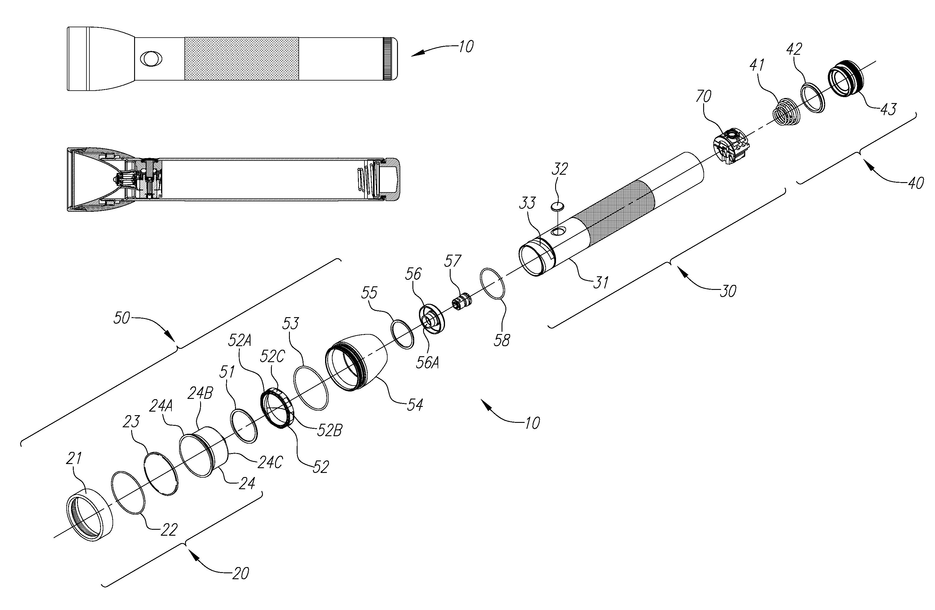
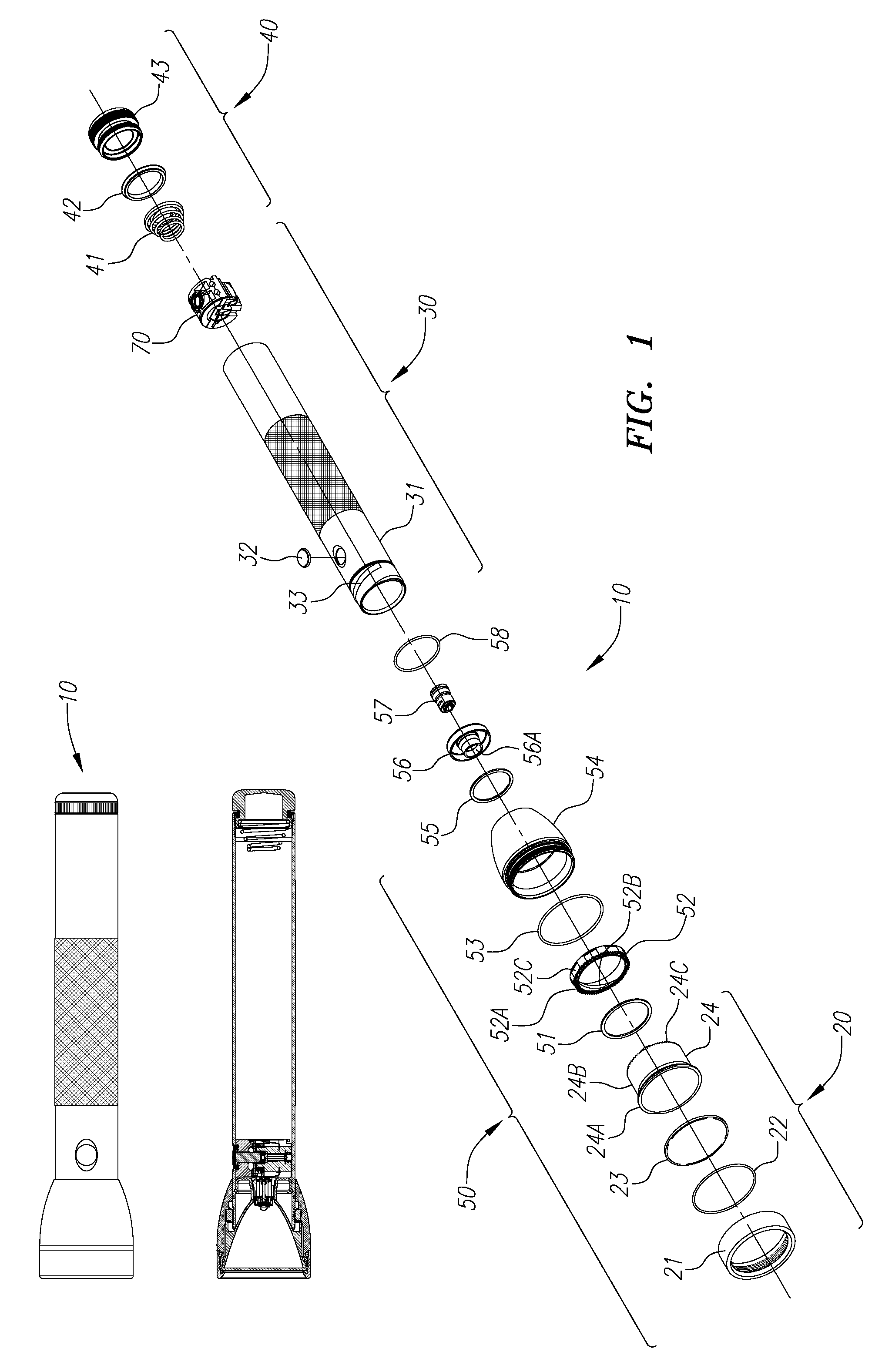
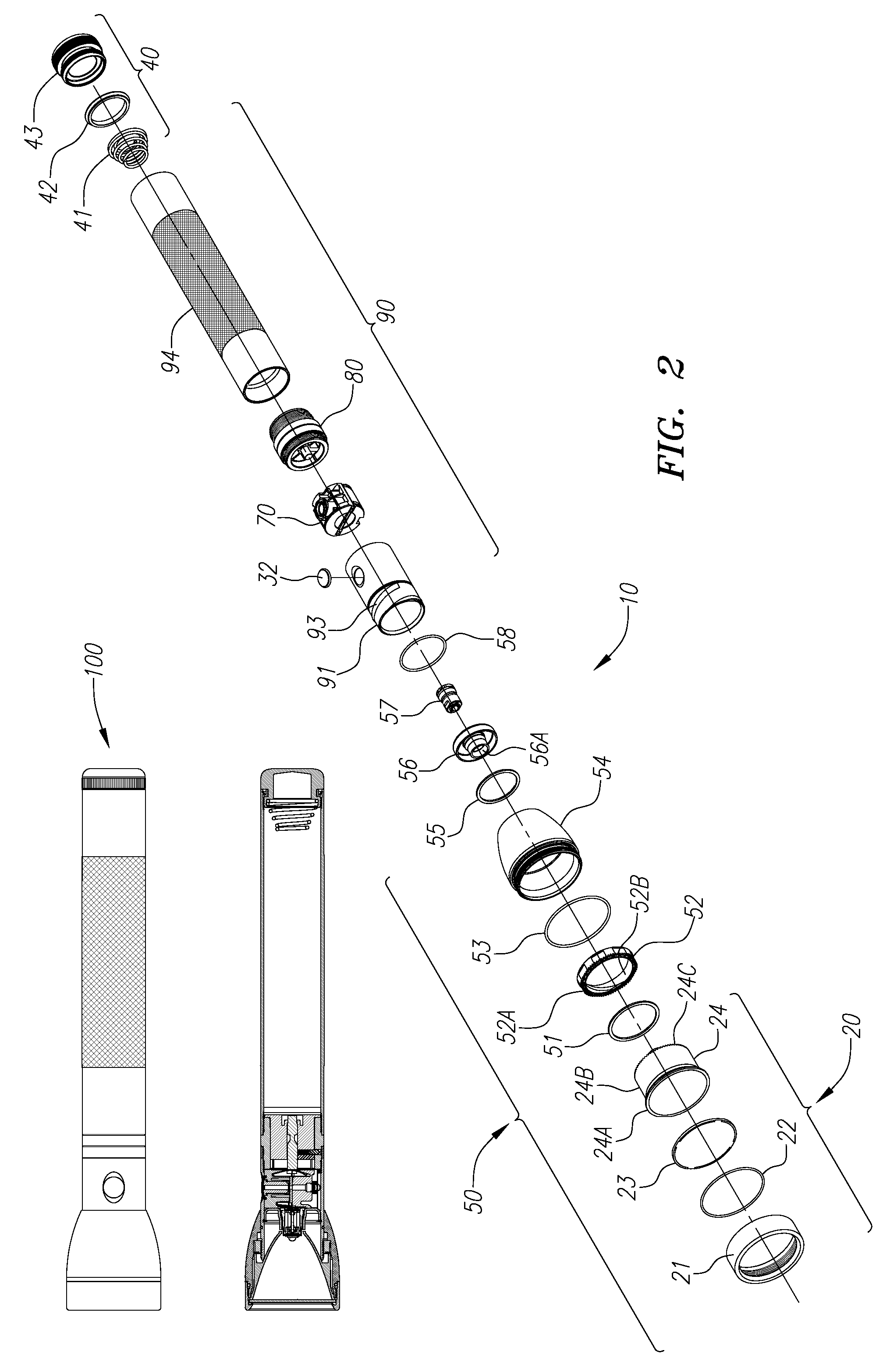
[0053]The overall design and operation of lighting devices reflecting the current invention are first described with reference to FIGS. 1 and 2. FIG. 1 shows a flashlight 10 having a non-rechargeable power source, while FIG. 2 shows a flashlight 100 having a rechargeable power source. The overall designs of rechargeable flashlight 100 and non-rechargeable flashlight 10 may be similar and may include a number of the same or similar components.

[0054]As shown in FIG. 1, flashlight 10 may generally comprise face cap assembly 20, barrel assembly 30, tail cap assembly 40, head assembly 50 and switch assembly 70. Similarly, as shown in FIG. 2, rech...


PUM


Abstract

Improved lighting devices, such as non-rechargeable and rechargeable flashlights, having simplified designs with fewer component parts are described. A focusing feature is described where the light source is held stationary and the reflector is moved through the engagement of threads and / or teeth arrangement. An improved reflector that avoids regions of increased thickness to reduce or avoid distortion caused by sink is also described.

Description

CROSS-REFERENCE TO RELATED APPLICATIONS[0001]The application claims the benefit of U.S. Provisional Application Ser. Nos. 61 / 751,935, filed Jan. 13, 2013, 61 / 791,905, filed Mar. 15, 2013, 61 / 839,362, filed Jun. 25, 2013 and 61 / 858,818, filed Jul. 26, 2013, the contents of which are incorporated by reference as if fully set forth herein.FIELD OF THE INVENTION[0002]The field of the invention relates to lighting devices, such as flashlights, that reflect simplified designs having fewer component parts, and that may include innovative focusing and reflector features, components that serve multiple functions, electronics and / or electronics packaging.BACKGROUND OF THE INVENTION[0003]Existing lighting devices, such as flashlights, typically involve a number of component parts. As the number of component parts increases, manufacturing costs may also increase and durability may decrease. That is, as the number of components increase, the cost to assemble them generally increases as does the ...

Claims


Application Information

Patent Timeline
Patent Type & Authority Patents(United States)
IPC IPC(8): F21L4/00F21V14/04
CPCF21V14/045F21L4/005
Inventor MAGLICA, ANTHONY
Owner MAG INSTR INC
Why Eureka
Try Eureka