Control circuit for burst switching of power converter and method thereof

a control circuit and power converter technology, applied in the direction of electric variable regulation, process and machine control, instruments, etc., can solve the problems of high output ripple at the output of the power converter, the problem of power saving in the switching mode power converter has drawn much attention, etc., and achieve the effect of higher efficiency

Active Publication Date: 2016-04-05
SEMICON COMPONENTS IND LLC
View PDF7 Cites 0 Cited by
  • Summary
  • Abstract
  • Description
  • Claims
  • Application Information

AI Technical Summary

Benefits of technology

[0005]An object of the present invention is to achieve lower power consumption and generate lower output ripple at the output of the power converter.
[0012]The present invention provides an adaptive threshold for the burst switching of power converter so as to achieve higher efficiency at light load condition and no load condition.

Problems solved by technology

In recent years, the problem of power saving in switching mode power converter has drawn much attention.
However, the drawback of this prior art is a higher output ripple at the output of the power converter.

Method used


Image

  • Control circuit for burst switching of power converter and method thereof
  • Control circuit for burst switching of power converter and method thereof
  • Control circuit for burst switching of power converter and method thereof

Examples


Embodiment Construction

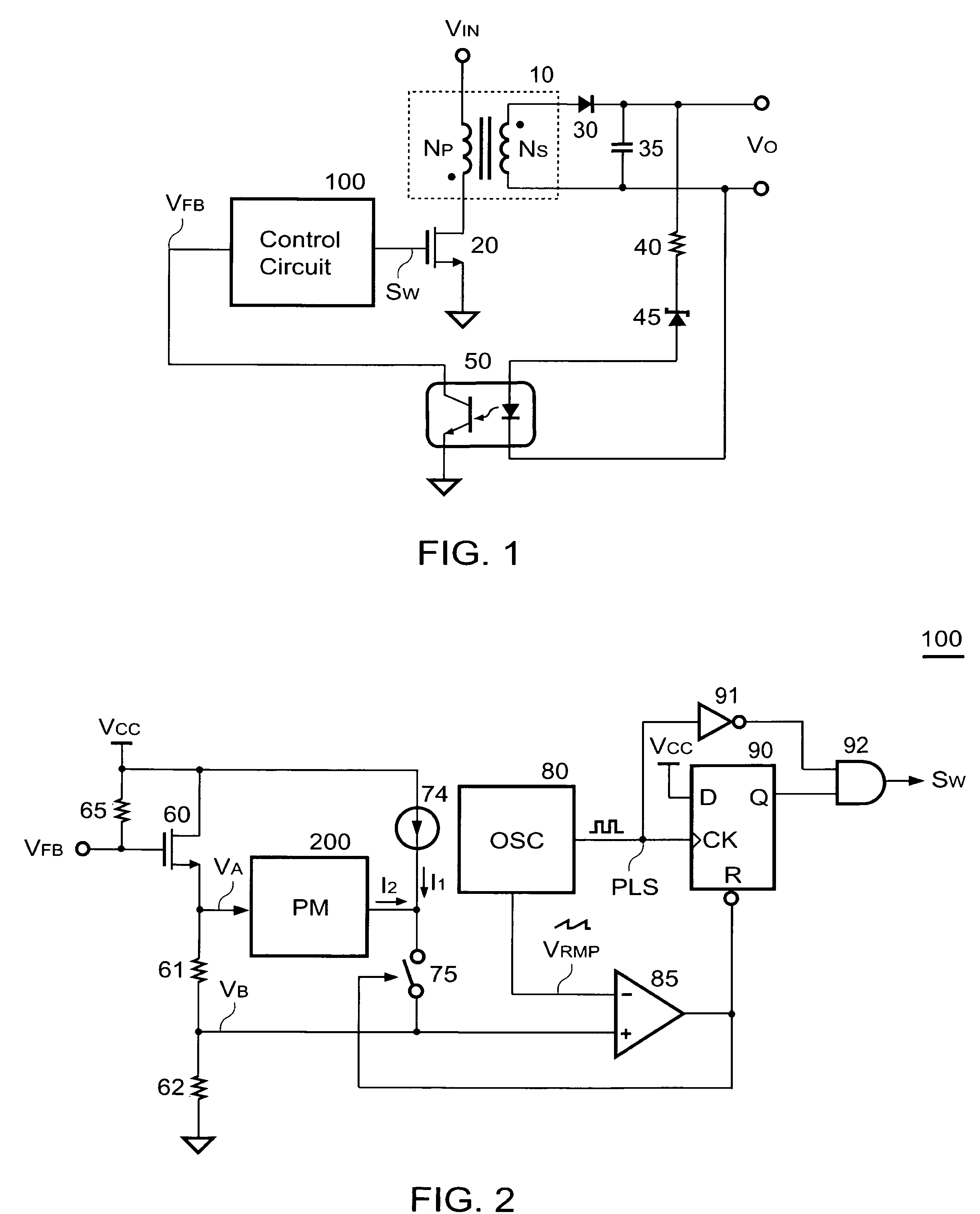
[0018]FIG. 1 shows a schematic circuit for a power converter. The power converter comprises a control circuit 100, a transformer 10, a transistor 20, a rectifier 30, a capacitor 35, a resistor 40, a reference device 45, and an opto-coupler 50. The control circuit 100 is coupled to the transistor 20 and controls the transistor 20 to generate a switching signal SW. The transformer 10 comprises a primary winding NP and a secondary winding NS. An input voltage VIN is supplied to one terminal of the primary winding NP. The transistor 20 is connected to the other terminal of the primary winding NP in series. The transistor 20 is used to switch the transformer 10 for transferring power energy from an input of the power converter to an output of the power converter. An output voltage VO is generated across the capacitor 35. The output voltage VO placed at the output of the power converter is regulated through the rectifier 30 and the capacitor 35.

[0019]Via the resistor 40, the reference dev...


PUM


Abstract

This invention provides a control circuit for burst switching of a power converter comprising: an adaptive circuit generating an adaptive threshold in response to a feedback signal correlated to an output load of the power converter; and a switching circuit generating a switching signal to switch a transformer of the power converter in accordance with the adaptive threshold and the feedback signal for regulating an output of the power converter.

Description

BACKGROUND OF THE INVENTION[0001]1. Field of Invention[0002]The present invention relates to a power converter, and more particularly, the present invention relates to a burst switching of power converter.[0003]2. Description of Related Art[0004]Switching mode power converter has been widely used to provide regulated voltage and current for computers, home appliances, communication equipments, etc. In recent years, the problem of power saving in switching mode power converter has drawn much attention. A prior art “Switching regulator having low power mode responsive to load power consumptions” U.S. Pat. No. 5,747,977 disclosed the skill using a threshold to achieve lower power consumption. However, the drawback of this prior art is a higher output ripple at the output of the power converter. This higher output ripple is caused by the threshold.SUMMARY OF THE INVENTION[0005]An object of the present invention is to achieve lower power consumption and generate lower output ripple at th...

Claims


Application Information

Patent Timeline
Patent Type & Authority Patents(United States)
IPC IPC(8): H02M3/335H02M1/00
CPCH02M3/33507H02M3/33515H02M2001/0035Y02B70/16H02M1/0035Y02B70/10
Inventor YANG, TA-YUNGHUANG, WEI-HSUANCHUNG, CHI-CHEN
Owner SEMICON COMPONENTS IND LLC
Why Eureka
Try Eureka