Emergency notification system

a technology of emergency notification and notification system, applied in the field of emergency notification system, can solve the problems of inability to caller may receive a busy signal, and the infrastructure does not offer any additional communication means

Inactive Publication Date: 2016-05-10
WEBB GRANT LEWIS
View PDF14 Cites 5 Cited by
  • Summary
  • Abstract
  • Description
  • Claims
  • Application Information

AI Technical Summary

Benefits of technology

[0008]Another object of the present invention is to provide an emergency notification system that includes a software application residing on a mobile device such as but not limited to a cellular phone, wherein the software application facilitates the dispersement of emergency request notifications.
[0017]Yet a further object of the present invention is to provide an emergency notification system that further provides the step of selecting a preferred first responder provider during the registration process of a user.
[0018]Still another object of the present invention is to provide an emergency notification system that further includes a server database that is operably coupled to the Internet wherein the system of the present invention provides real-time visibility to all emergency request notifications within a designated region to a registered emergency medical service (EMS) provider.

Problems solved by technology

One issue with the current national 911 Service emergency alert notification system is that the caller may receive a busy signal.
This obviously can result in the loss of life or delays in an emergency victim's emergency medical care.
The current 911 infrastructure does not offer any additional means of communicating with the emergency operation centers and as a result there have been recorded instances of lives lost due to the current system limitations.
Another issue with the current 911 service is the lack of available medical information regarding the emergency victim.

Method used


Image

  • Emergency notification system
  • Emergency notification system
  • Emergency notification system

Examples


Embodiment Construction

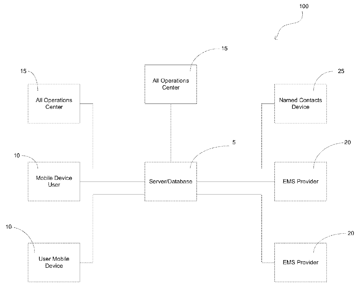
[0035]Referring now to the drawings submitted herewith, wherein various elements depicted therein are not necessarily drawn to scale and wherein through the views and figures like elements are referenced with identical reference numerals, there is diagrammed an emergency notification system 100 constructed according to the principles of the present invention.

[0036]Now referring in particular to FIG. 1 herein, a general block diagram of the system components and architecture are illustrated therein. The emergency notification system 100 includes a server-database 5 that provides the core functionality of the present invention. The server-database 5 includes the necessary electronics to store, receive, transmit and manipulate data. The server-database 5 includes the necessary software program to execute the method of the present invention as described herein. The server-database 5 is embodied as a conventional computer server and is operably coupled to the Internet using suitable comm...


PUM


Abstract

An emergency notification system and method that is operable to provide a technique for a user to transmit an emergency signal request wherein the emergency signal request is transmitted to a 911 operations center, registered EMS providers, and at least one named contact identified by the user transmitting the emergency signal request simultaneously. The emergency notification system includes a server database having control software and further includes a software application for mobile devices. The emergency notification system is operable to receive and store relevant medical data for each of the registered users of the system wherein the medical data is transmitted to emergency medical service providers during the transmission of the emergency signal request. A customized notification message is additionally sent to a predefined list of contacts during the emergency signal request. The customized notification message further includes the geographic coordinates of the user transmitting the emergency signal request.

Description

PRIORITY UNDER 35 U.S.C. Section 119(e) & 37 C.F.R. Section 1.78[0001]This nonprovisional application claims priority based upon the following prior U.S. Provisional Patent Application entitled: Emergency iSystems a real time emergency communication interface, Application No. 61 / 967,928 filed Mar. 31, 2014, in the name of Grant Lewis Webb, which is hereby incorporated by reference for all purposes.FIELD OF THE INVENTION[0002]The present invention relates generally to notification systems, more specifically but not by way of limitation, an emergency notification system that utilizes a combination of mobile devices, servers and the Internet to facilitate a user issued notification to multiple emergency service providers in the event of an emergency.BACKGROUND[0003]In the United States an estimated 240 million emergency calls are made to 911 each year. According to the FCC and the national 911 service, greater than 71% of these calls are made using cellular telephones while approximate...

Claims


Application Information

Patent Timeline
Patent Type & Authority Patents(United States)
IPC IPC(8): H04M11/04H04W4/22H04W4/90
CPCH04W4/22H04W4/90
Inventor WEBB, GRANT LEWIS
Owner WEBB GRANT LEWIS
Why Eureka
Try Eureka