Irrigated catheter with fluid evacuation

a technology of irrigated catheters and catheters, which is applied in the field of electrophysiologic catheters, can solve the problems of increasing the fluid load in the patient, increasing the number of catheters in the body, and forming a lesion within the cardiac tissue which is electrically non-conductive,

Active Publication Date: 2016-06-07
BIOSENSE WEBSTER (ISRAEL) LTD
View PDF24 Cites 9 Cited by
  • Summary
  • Abstract
  • Description
  • Claims
  • Application Information

AI Technical Summary

Problems solved by technology

The tissue is heated sufficiently to cause cellular destruction in the cardiac tissue resulting in formation of a lesion within the cardiac tissue which is electrically non-conductive.
Moreover, current catheters include irrigated ring electrodes further increasing the fluid load in the patient.
The pericardial space can quickly begin to fill with the irrigation fluid, such as saline, thereby limiting the amount of time the ablation catheter can be in the body and the number of ablations that can be performed due to fluid overload.

Method used


Image

  • Irrigated catheter with fluid evacuation
  • Irrigated catheter with fluid evacuation
  • Irrigated catheter with fluid evacuation

Examples


Embodiment Construction

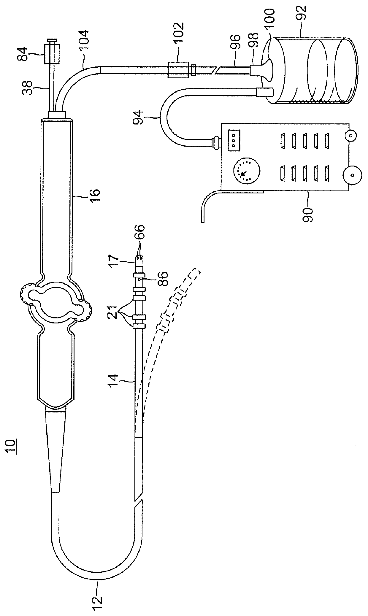
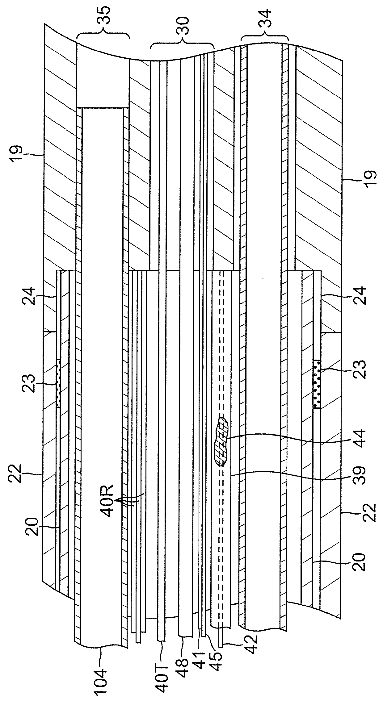
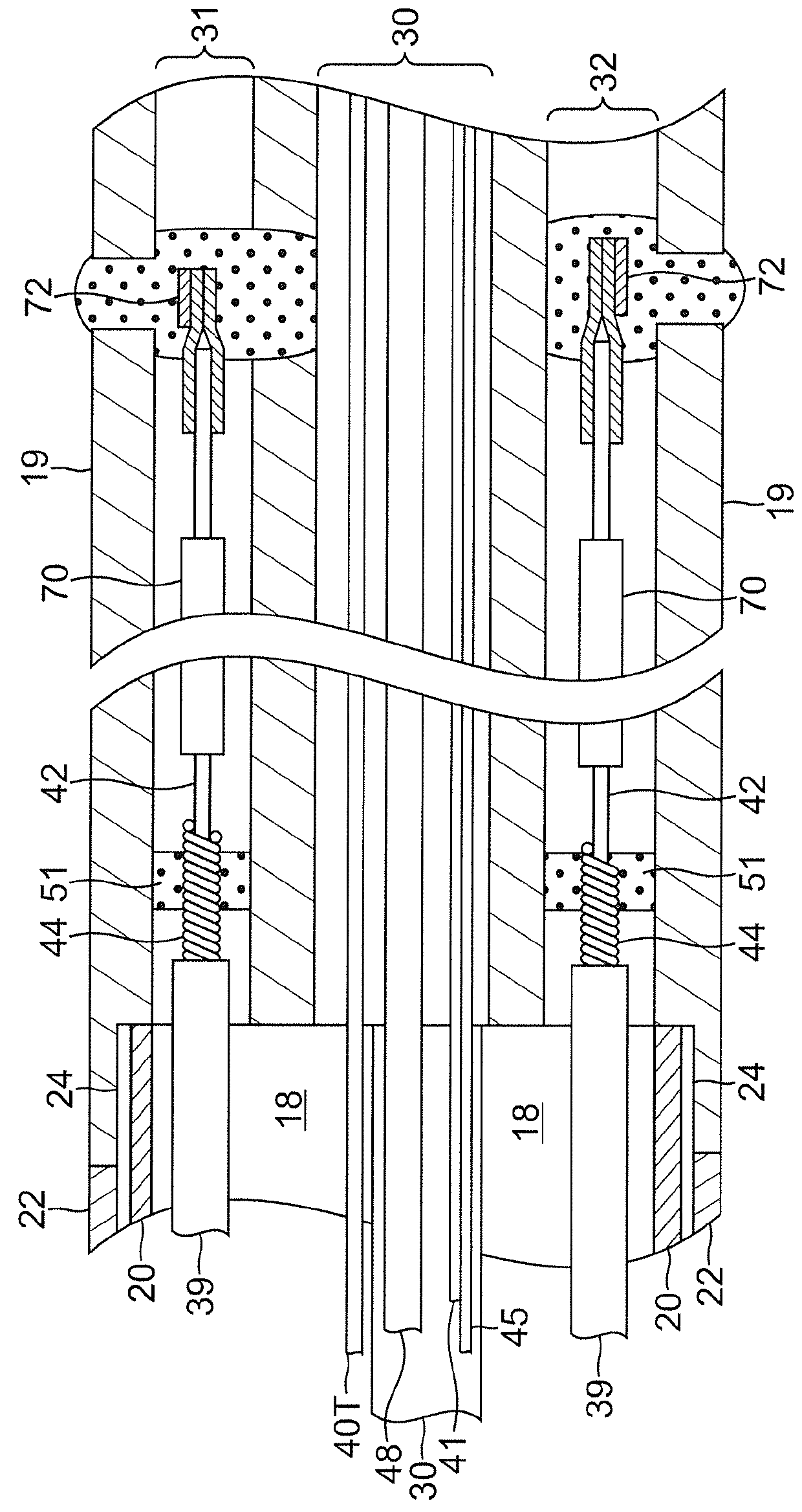
[0023]In an embodiment of the invention, there is provided a steerable bi-directional catheter having an irrigated tip and fluid evacuation adaptations. As shown in FIGS. 1-3, catheter 10 comprises an elongated catheter body 12 having proximal and distal ends, a deflectable distal tip section 14 at the distal end of the catheter body 12, and a control handle 16 at the proximal end of the catheter body 12.

[0024]With reference to FIGS. 1 and 2A, the catheter body 12 comprises an elongated tubular construction having a single, axial or central lumen 18. The catheter body 12 is flexible, i.e., bendable but with substantially torsional stiffness. The catheter body 12 can be of any suitable construction and made of any suitable material. In the illustrated embodiment, the catheter body 12 has an outer wall 22 made of a polyurethane or PEBAX. The outer wall 22 comprises an imbedded braided mesh of stainless steel or the like to increase torsional stiffness of the catheter body 12 so that, ...


PUM


Abstract

A catheter for use with a suction source for removing excess fluid from a tissue treatment site has a catheter body, a distal section and a fluid evacuation path, where the distal section includes a multi-lumened member and at least one evacuation port, and the fluid evacuation path extends through a lumen in the multi-lumened member to provide suction communication between the suction source and the at least one evacuation port. The fluid evacuation path may also be configured for two-way flow, including distally and proximally along the catheter.

Description

FIELD OF INVENTION[0001]The present invention relates to an electrophysiologic catheter that is particularly useful for ablation and sensing electrical activity of heart tissue.BACKGROUND OF INVENTION[0002]Electrode catheters have been in common use in medical practice for many years. Diagnosis and treatment of cardiac arrythmias by means of electrode catheters include mapping the electrical properties of heart tissue and selectively ablating cardiac tissue by application of energy. Such ablation can cease or modify the propagation of unwanted electrical signals from one portion of the heart to another. The ablation process destroys the unwanted electrical pathways by formation of non-conducting lesions. Various energy delivery modalities have been disclosed for forming lesions, and include use of microwave, laser and more commonly, radiofrequency energies to create conduction blocks along the cardiac tissue wall.[0003]In a two-step procedure—mapping followed by ablation—electrical ...

Claims


Application Information

Patent Timeline
Patent Type & Authority Patents(United States)
IPC IPC(8): A61B18/14A61B18/08A61B18/00
CPCA61B18/082A61B18/1492A61B2018/00029A61B2018/00035A61B2018/00166A61B2018/00577A61B2018/00821A61B2034/2051A61B2218/001A61B2218/002A61B2218/007A61M2025/015A61B2018/1405
Inventor PLASCENCIA, JR., ROGELIOPONZI, DEANTUASON, ARNOLD
Owner BIOSENSE WEBSTER (ISRAEL) LTD
Why Eureka
Try Eureka