Variable angle bone screw fixation arrangement

a fixed arrangement and variable angle technology, applied in the field of fixed devices, can solve the problems of limiting the application of pressing force, affecting the safety of fastening, etc., and achieve the effect of good positioning accuracy

Inactive Publication Date: 2016-09-27
FACET LINK
View PDF235 Cites 2 Cited by
  • Summary
  • Abstract
  • Description
  • Claims
  • Application Information

AI Technical Summary

Benefits of technology

[0031]In all embodiments the bone screw can be provided with a continuous borehole running along its central axis, i.e., it is cannulated. Thus, it can be inserted along a guide wire that is pushed through, accomplishing a very good positioning accuracy even under difficult access conditions.

Problems solved by technology

Large tightening forces can twist the support sleeve, which endangers the fastening safety.
This design limits the pressing forces which can be applied, and thus the clamping forces needed to achieve an angle stability.

Method used


Image

  • Variable angle bone screw fixation arrangement
  • Variable angle bone screw fixation arrangement
  • Variable angle bone screw fixation arrangement

Examples


first embodiment

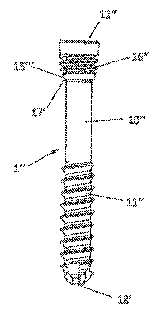
[0054]One variant of the first embodiment is shown in FIGS. 10 and 11. Similar parts have the same reference numbers. The major difference lies in the configuration of the sleeve 8 and the tension cage 9. The sleeve 8 is a hollow cylinder with an inner bore 80 running through it from a rear end to the front end, being provided in its rear region with an internal thread 81 to accommodate the pressing element 5 and in its front region with a segment 82′ of a snug fit 82 that is shaped as a hollow spherical segment. In the middle region there is provided an essentially smooth inner wall, against which the tension cage 9 bears with its envelope surface 90. The hollow spherical segment 82′ of the snug fit 82 is shaped complementary to the ball head 12 of the bone screw 12. The opening at the front end of the sleeve 8 is narrowed and lets the shaft 10 pass through, but prevents the ball head 12 from going through.

[0055]The sleeve 8 furthermore has two diametrically opposite lengthwise slo...

second embodiment

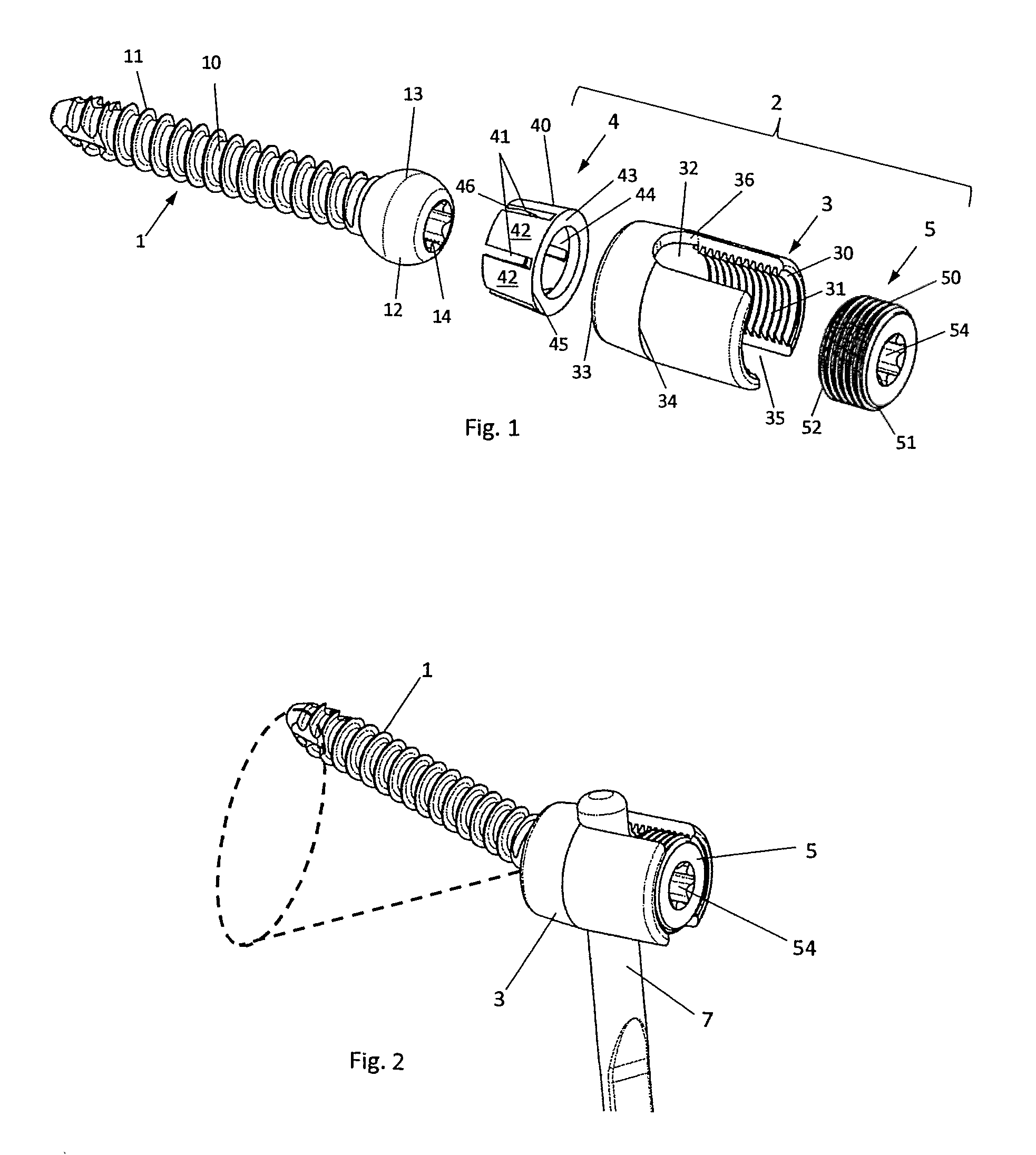
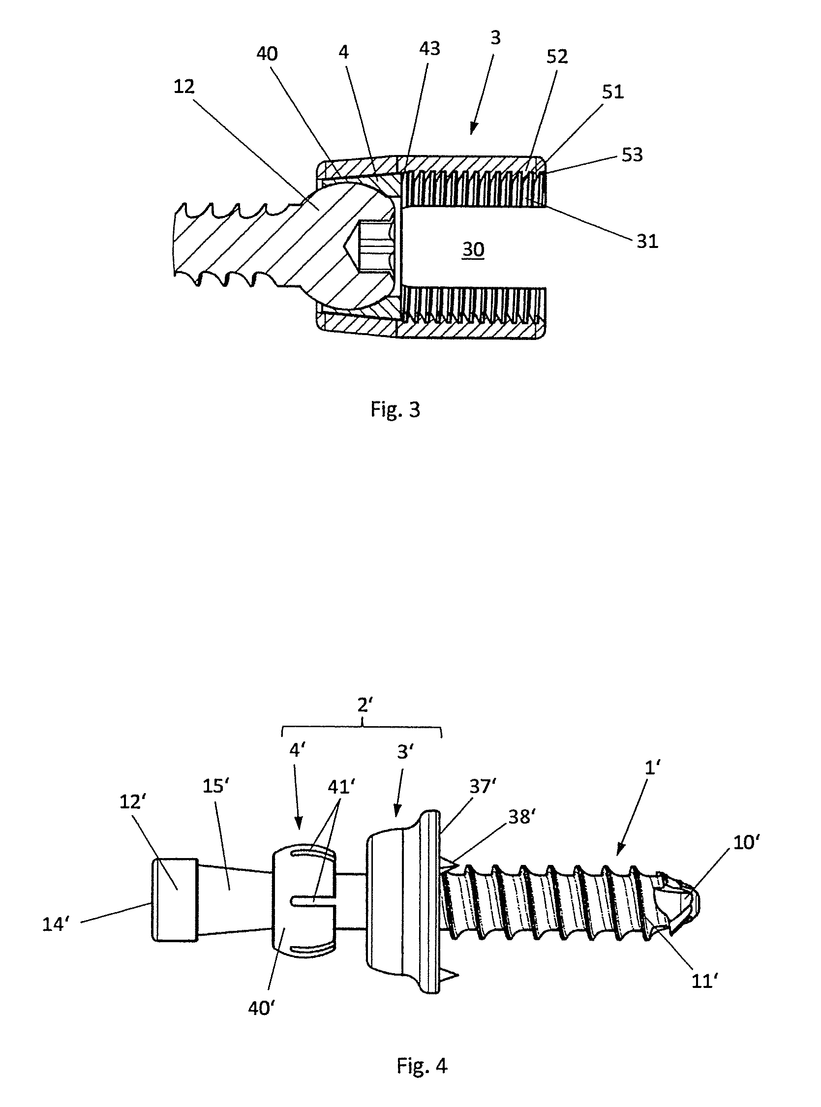
[0058]We shall now refer to the As can be seen from FIG. 4, the fixation apparatus comprises a holder 2′ for a bone screw 1′, having a shaft 10′ with a bone thread 11′ disposed in the forward region. Toward the rear end, the shaft 10′ has an increasing thickness 15′. It extends as far as a head 12′, which has a depression 14′ to accommodate a screwdriver (not shown).

[0059]The holder 2′ comprises a base plate 3′ and a tension sleeve 4′. The base plate 3′ has a bearing surface 37′ at its front end to bear against a bone or other tissue parts. It can be provided with optional support spikes 38′.

[0060]The base plate 3′ has a support opening 30′ passing through it, being widened to a snug fit 32′ in the shape of a spherical dome in its middle region. This receives the tension sleeve 4′, which in turn has a spherical envelope surface 40′ with suitable dimensions. The tension sleeve 4′ is mounted and able to swivel thanks to the complementary surfaces of the spherical envelope surface 40′...


PUM


Abstract

A fixation apparatus comprises a holder and a tension sleeve receiving a bone screw, wherein the bone screw has a shaft with a front thread and a head at the rear end, and the holder has a through borehole with a receiving seat, in which the tension sleeve is mounted and able to swivel, while the shaft has a thickening in a rear region, to the front of the head, whose width increases toward the head, and the width of the tension sleeve is larger than the width of the shaft immediately before the thickening and smaller than the greatest width of the thickening. When screwed in, the thickening widens the tension sleeve so that it is pressed by its envelope against the wall of the receiving seat. In this way, an angle-stable pressing is achieved for any given orientation of the bone screw.

Description

CROSS REFERENCE TO RELATED APPLICATIONS[0001]This application claims the benefit of U.S. Provisional Application No. 61 / 418,662, filed Dec. 1, 2010. This application also claims the priority of European Patent Application No. 10015172.9, filed Dec. 1, 2010.FIELD OF THE INVENTION[0002]The invention relates to a fixation apparatus for fastening by means of a bone screw. The fixation apparatus serves in particular for connection to a support rod for an implant, but it can also be used by itself.BACKGROUND OF THE INVENTION[0003]Screws are often used for a removable yet also sufficiently firm attachment of implants. Depending on the application, a rigid-angle positioning between the implant and the bone screw is sufficient; in other cases, however, a variable-angle (polyaxial) arrangement of the bone screws is required. Such a polyaxially mounted bone screw for a fixation apparatus is known in its basic features from EP 0 614 649 B1. The bone screw is led through a support sleeve, which ...

Claims


Application Information

Patent Timeline
Patent Type & Authority Patents(United States)
IPC IPC(8): A61B17/70A61B17/80A61B17/86
CPCA61B17/7037A61B17/8047A61B17/863A61B17/8605A61B17/809A61B17/86A61B17/70A61B17/80
Inventor JENSEN, HARM-IVENLINK, HELMUT D.
Owner FACET LINK
Why Eureka
Try Eureka