LED lighting strip

Active Publication Date: 2016-10-11
MORGAN
View PDF8 Cites 3 Cited by
  • Summary
  • Abstract
  • Description
  • Claims
  • Application Information

AI Technical Summary

Benefits of technology

[0004]The present invention seeks to provide a solution to this problem by providing lighting units which can be rapidly assembled into a lighting arrangement to provide the required amount of light and to enable the individual lights to be directed in the required direction sub

Problems solved by technology

Such an installation is therefore almost inevitably e

Method used


Image

  • LED lighting strip
  • LED lighting strip
  • LED lighting strip

Examples


Example

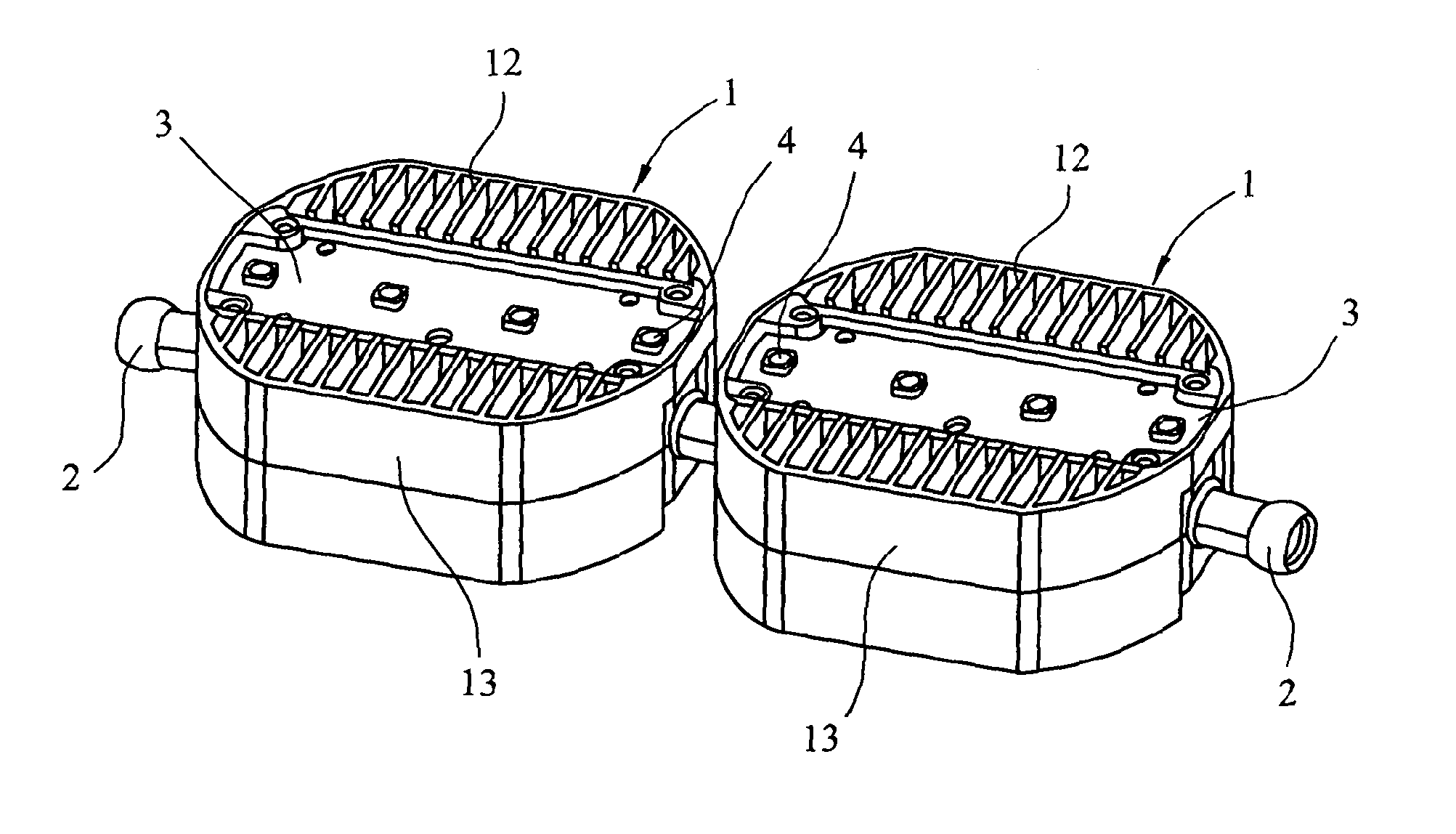
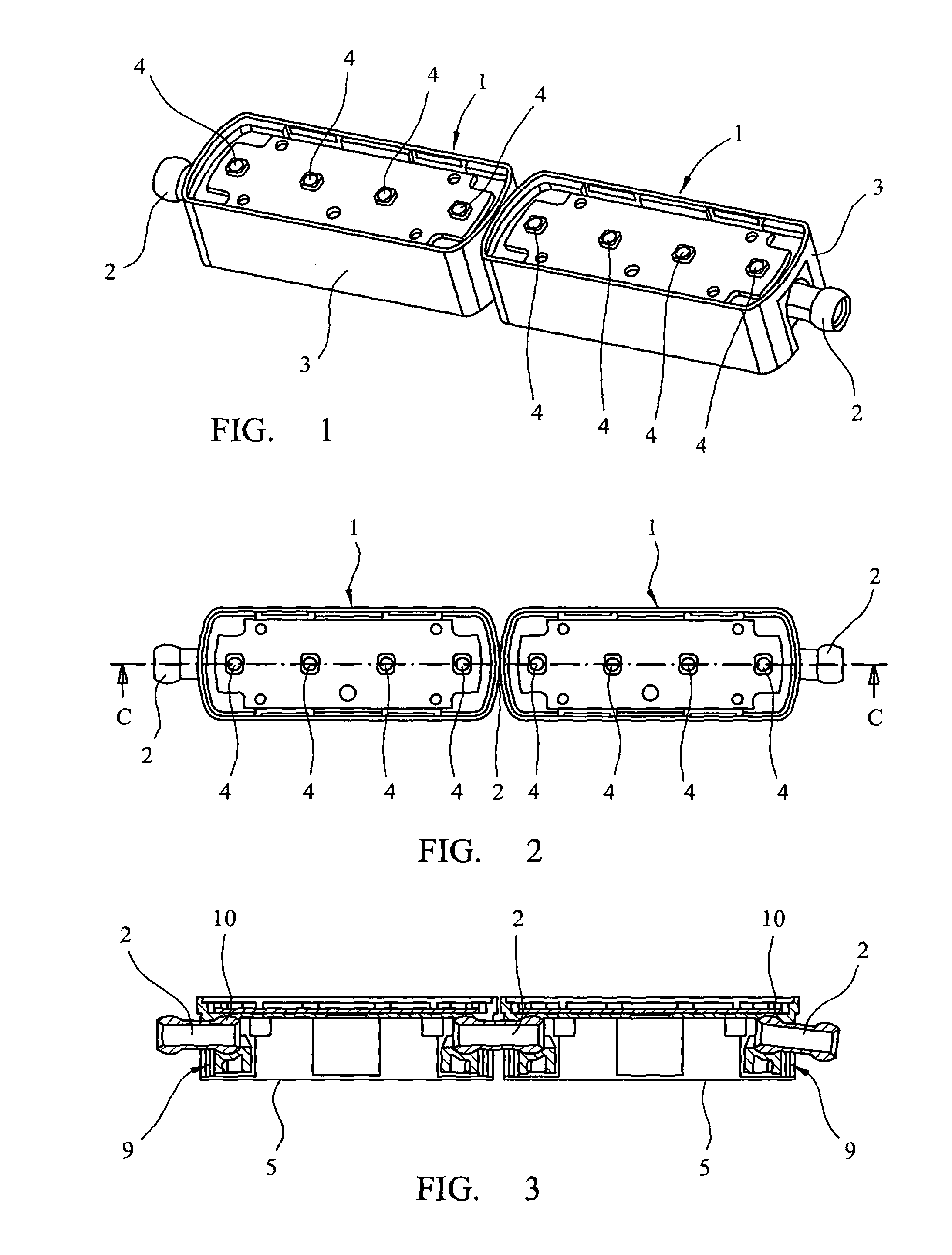
[0023]Referring now to FIGS. 1-4, there is shown an embodiment of a lighting arrangement consisting of two lighting units 1 joined together by a ball joint arrangement 2. Each lighting unit 1 consists of a main body 3 in the form of an elongate holder having mounted on one face a series of linearly aligned light sources 4 in the form of LEDs mounted on a plate which is secured to the main body 1. As shown in FIG. 2, the light sources 4 are linearly aligned along the central axis of the light units 1. The main body 3 also forms a heat sink to assist in dissipating the heat generated by the light sources 4 in use.

[0024]The electrical wiring for the lights, and a power cable are contained, in use, within the main body 3 but are not shown. The opposite face of the main body to the light sources is closed by a retaining plate 5.

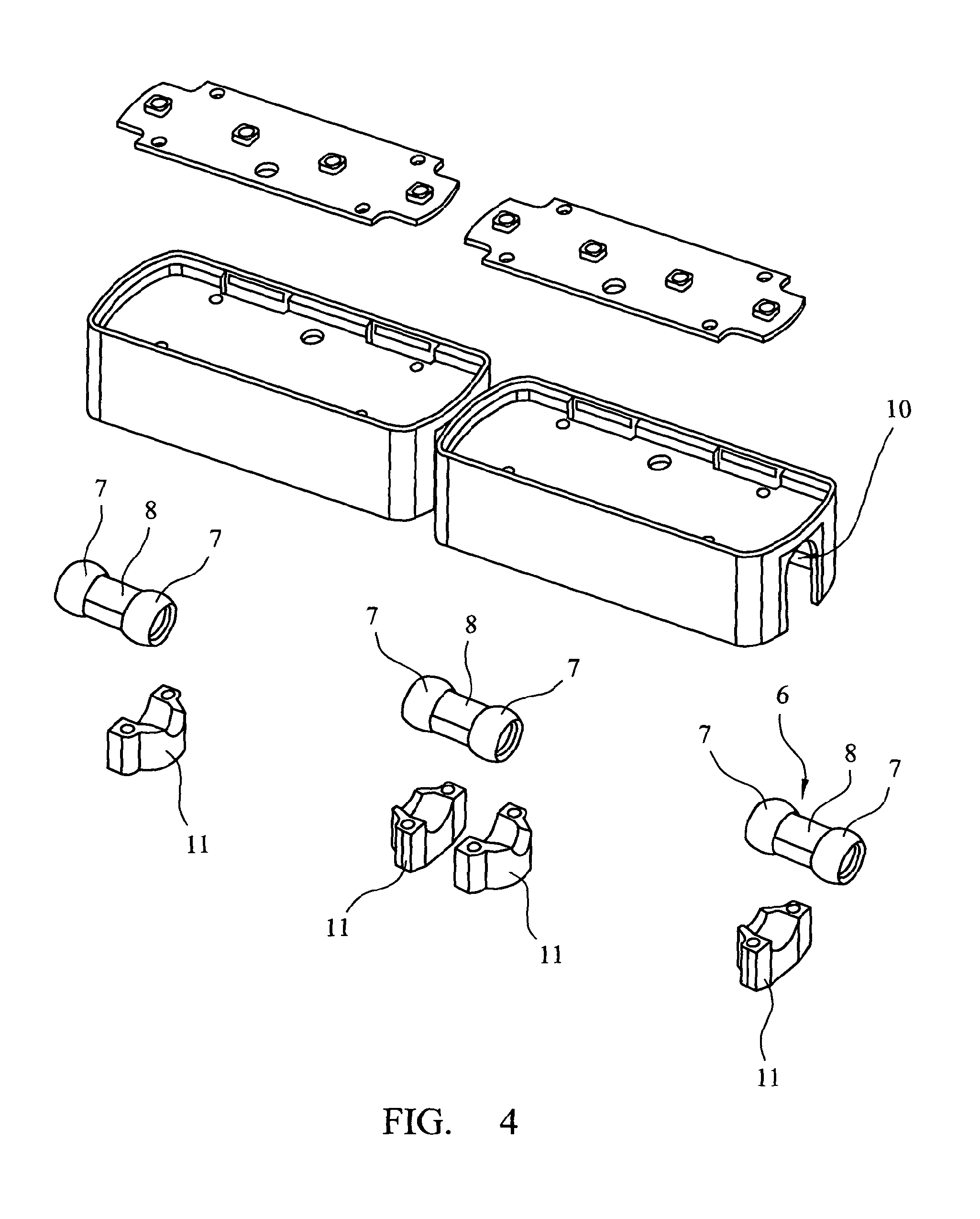
[0025]As shown particularly in FIGS. 3 and 4, the two light units 1 are adjoined by a ball joint arrangement 2 each of which comprises a pair 6 of conjoined balls...


PUM


Abstract

An electric lighting arrangement including a plurality of lighting units each containing a plurality of LED lights, to form a strip of lights. The units are adapted to be joined together by means of a ball joint arrangement, which comprises two conjoined balls, each ball being adapted to be mounted in a retaining bail cup in a lighting unit, ball cups being provided on opposed ends of the units to enable the units to be pivotable one relative to the other in all planes. Each lighting unit includes a main body incorporating a heat sink in the form of head conducting fins.

Description

CROSS-REFERENCE TO RELATED APPLICATION(S)[0001]This is a National Stage Entry into the United States Patent and Trademark Office from International PCT Patent Application No. PCT / GB2012 / 000831, having an international filing date of Nov. 6, 2012, and which claims priority to United Kingdom Patent Application No. GB 1119163.2, filed Nov. 7, 2011, the entire contents of both of which are incorporated herein by reference.FIELD OF THE INVENTION[0002]The present invention relates to lighting arrangements, particularly but not exclusively, for providing distinctive lighting patterns to areas such as auditoria, commercial reception areas public spaces and hotel lounges.DESCRIPTION OF THE RELATED ART[0003]In such large areas there is a requirement for lighting systems which, particularly when dealing with complex shaped spaces, require a significant amount of flexibility to enable the light to be directed in the direction and with the intensity required for the desired lighting effect. Typi...

Claims


Application Information

Patent Timeline
IPC IPC(8): F21S4/00F21V23/06F21V21/005F21V29/83F21Y103/00
CPCF21S4/20F21S4/28F21V21/005F21V23/06F21V29/83F21Y2101/00F21Y2103/10F21Y2115/10F21V29/763F21S4/22F21V23/001F21S2/005
Inventor MORGAN
Owner MORGAN
Why Eureka
Try Eureka