Latency-reducing image generating system, device, and method

a technology of image generating system and image generating process, which is applied in the direction of process and machine control, instruments, etc., can solve the problems of inherent latency in the speed of image generating processors in general continues to increase, and the inherent latency induced by the image generating process, etc., to and reduce image generating latency

Active Publication Date: 2017-06-06
ROCKWELL COLLINS INC
View PDF20 Cites 4 Cited by
  • Summary
  • Abstract
  • Description
  • Claims
  • Application Information

AI Technical Summary

Benefits of technology

[0006]The embodiments disclosed herein present at least one novel and non-trivial system, device, and method for reducing the latency when generating an image. With the embodiments disclosed herein, the scene viewed by the pilot on the display unit will more closely match the actual scene located outside the aircraft.
[0007]In one embodiment, a system is disclosed for reducing image generating latency. The system may be comprised of a navigation data source and an image processing unit (“IPU”). The image data set could be representative of a predicted image of the scene outside an aircraft, where instant navigation data provided by the navigation data source may be used to determine predictive navigation data upon which the image data set is generated. Additionally, the system could include a source of an image data from which the image data set is generated, and a display system for presenting the image of on one or more display units.
[0008]In another embodiment, a device such as the IPU is disclosed for reducing image generating latency. This device may be configured to select a subset of the image data set based upon a comparison of two sets of navigation data acquired at different times. Differences arising from the comparison may be used in determining the location and / or rotation of a cropping frame within which the subset is selected and a cropped image is formed that is subsequently presented on the display unit.
[0009]In another embodiment, a method is disclosed for reducing image generating latency. When properly configured, the IPU may receive the image data set; receive (1) first navigation data of the first time from which second navigation data of the second time is determined or (2) second navigation data of the second time; receive third navigation data of the second time; compare the second navigation data with the third navigation data; and select a subset of the image data set in response to the comparison. In an additional embodiment, the IPU may provide the subset of the image data set to the display system, whereby the image represented in such subset is presented on one or more display units.

Problems solved by technology

Although the display of such image is beneficial to the pilot, the performance of the above-discussed steps creates an inherent latency in the image generation process.
Although the speed of image generating processors in general continues to increase, there nevertheless exists an inherent latency induced by the image generating process.

Method used


Image

  • Latency-reducing image generating system, device, and method
  • Latency-reducing image generating system, device, and method
  • Latency-reducing image generating system, device, and method

Examples


Embodiment Construction

[0028]In the following description, several specific details are presented to provide a thorough understanding of embodiments of the invention. One skilled in the relevant art will recognize, however, that the invention can be practiced without one or more of the specific details, or in combination with other components, etc. In other instances, well-known implementations or operations are not shown or described in detail to avoid obscuring aspects of various embodiments of the invention.

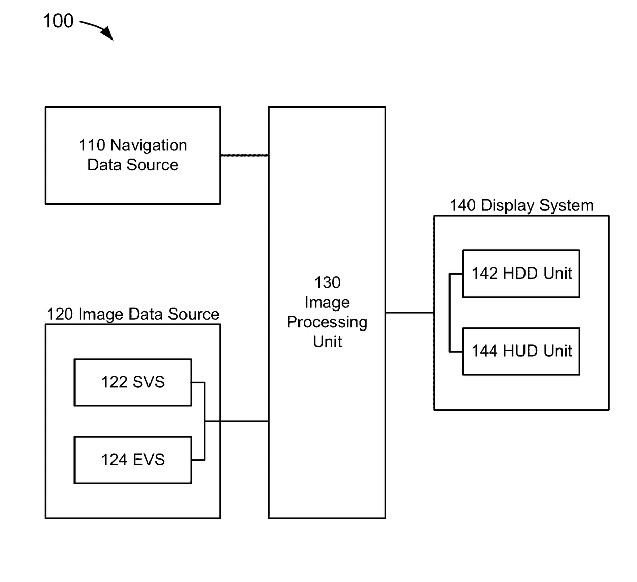
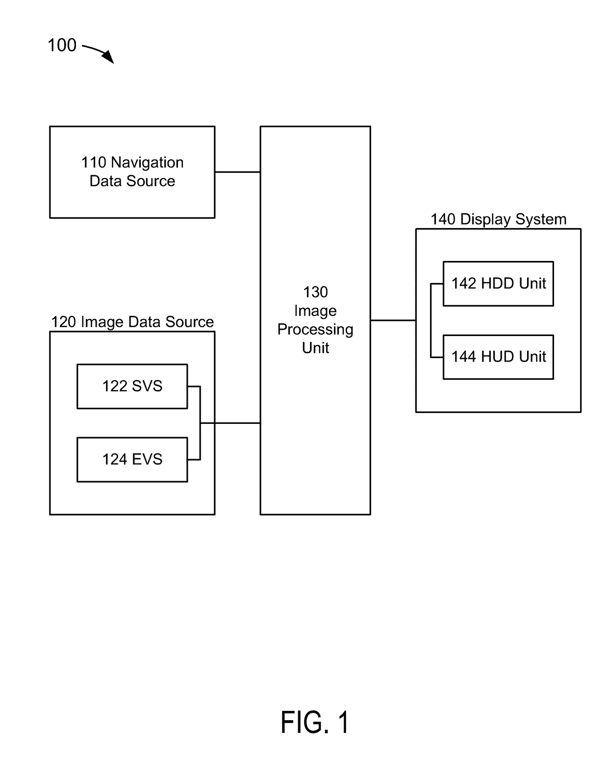
[0029]FIG. 1 depicts a block diagram of a reduced latency, image generating system 100 suitable for implementation of the techniques described herein. The image generating system 100 of an embodiment of FIG. 1 includes a navigation data source 110, an image data source 120, an image processing unit (“IPU”) 130, and a display system 140.

[0030]In an embodiment of FIG. 1, the navigation data source 110 could be comprised of a system or systems that provide navigation data information in an aircraft. Fo...


PUM


Abstract

A present novel and non-trivial system, device, and method for reducing image generating latency of an image presented on a display unit are disclosed. An image processing unit (“IPU”) may receive the image data set; receive (1) first navigation data of a first time from which second navigation data of the second time is determined or (2) second navigation data of a second time; receive third navigation data of the second time; compare the second navigation data with the third navigation data; and select a subset of the image data set in response to the comparison. Differences arising from the comparison, if any, may be used in determining the location and / or rotation of a cropping frame that selects the subset and forms a cropped image which is then provided to a display system, whereby the image represented in the subset is presented to the viewer.

Description

BACKGROUND OF THE INVENTION[0001]Field of the Invention[0002]This invention pertains generally to the field of vehicles display units such as an aircraft display unit that provide information to the vehicle operator such as a pilot of an aircraft.[0003]Description of the Related Art[0004]The presentation a three-dimensional perspective of an image of the scene outside the aircraft is common. Prior to presenting the image, an image generating process must be performed. Generally, navigation data representative of the aircraft position (e.g., latitude, longitude, and altitude) and aircraft direction (e.g., heading) is used to retrieve terrain and / or obstacle data. Once this data is retrieved, an image data set representative of an image of a realistic, three-dimensional perspective of the scene outside the aircraft may be generated, provided to the display system, and subsequently displayed to the pilot.[0005]Although the display of such image is beneficial to the pilot, the performan...

Claims


Application Information

Patent Timeline
Patent Type & Authority Patents(United States)
IPC IPC(8): G01C23/00G05D1/00G01C21/00B64D45/00G01S19/15G08G5/00
CPCB64D45/00G09G2340/10G01S19/15G08G5/0021G01C23/00G01C23/005G09G5/377G09G2380/12
Inventor TIANA, CARLO L.LAHR, WESTON J.
Owner ROCKWELL COLLINS INC
Why Eureka
Try Eureka