Method and device for multiple-serving-cell connectivity for UE and base station

a technology of ue and base station, applied in the field of dual-connectivity communication uplink power control methods and devices, can solve problems such as the problem of solving the power reduction of the pucch signal transmitted by the secondary base station, and achieve the effect of maintaining maximum compatibility and robustness of the ue connection

Active Publication Date: 2017-08-29
SISVEL INT
View PDF7 Cites 2 Cited by
  • Summary
  • Abstract
  • Description
  • Claims
  • Application Information

AI Technical Summary

Benefits of technology

[0016]The character of the above aspect is that when the power reduction is performed, the priority of the PUCCH transmitted to the cell maintained by the secondary base station is lower than the priority of the PUCCH transmitted to the cell maintained by the primary base station. Thus, the advantage is that it is capable of ensuring the receiving quality of PUCCH in the primary base station, thereby ensuring the robustness of the UE connection.
[0063]wherein the third uplink signal is a PUSCH with a UCI, the third power is a smaller value between a difference value and a third ideal power, the difference value is obtained by subtracting the first power and the second power from the maximum total transmitting power. The third ideal power is a transmitting power of the third uplink signal without performing the power reduction; the power is a linear value. The K serving cells do not include the third serving cells, the k is a positive integer from 1 to K, and the K is a positive integer. A sum of the power P1, P2, . . . , PK does not exceed a difference value obtained by subtracting the first power, the second power and the third power from the maximum total transmitting power. The power Pk is the product of the power reduction factors w and Pkideal of the first sub frame. The Pkideal is a transmitting power of the Sk when the power reduction does not perform. The w is configurable.
[0074]For a problem of the power reduction of a PUCCH that may be caused by transmitting the PUCCH on a secondary cell (a cell maintained by a secondary base station) in a dual-connectivity communication, the present invention disclose a scheme for the power reduction of the PUCCH in the dual-connectivity communication. In one embodiment, when the power reduction is performed, a priority of the PUCCH transmitted on a secondary cell is lower than a priority of the PUCCH transmitted on a primary cell (a cell maintained by a primary base station). The present invention is capable of ensuring a receiving quality of the PUCCH on the primary cell, thereby ensuring a robustness of the UE connection. Moreover, the present invention maintains maximum compatibility with present system.

Problems solved by technology

When a transmitting power of the UE in the dual-connectivity communication exceeds a maximum total transmitting power, how to perform a power reduction for the PUCCH signal transmitted by the cell maintained by the secondary base station is a problem to be solved.

Method used


Image

  • Method and device for multiple-serving-cell connectivity for UE and base station
  • Method and device for multiple-serving-cell connectivity for UE and base station
  • Method and device for multiple-serving-cell connectivity for UE and base station

Examples


embodiment i

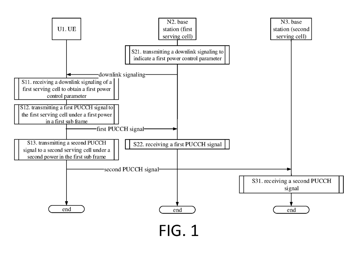
[0084]Embodiment I illustrates a flowchart of transmitting PUCCH signals on a primary cell and a secondary cell simultaneously, as shown in FIG. 1. In FIG. 1, the base station N2 is a maintaining base station of the first serving cell, i.e. a primary base station, and the base station N3 is a maintaining base station of the second serving cell, i.e. a secondary base station.

[0085]For the UE U1, in step S11, the method involves receiving a downlink signaling of a first serving cell to obtain a first power control parameter; in step S12, the method involves transmitting a first PUCCH signal to the first serving cell under a power P1PUCCH in a first sub frame; in step S13, the method involves transmitting a second PUCCH signal to a second serving cell under a power P2PUCCH in the first sub frame.

[0086]For the base station N2, in step S21, the method involves transmitting a downlink signaling to indicate a first power control parameter; in step S22, the method involves receiving a first...

embodiment ii

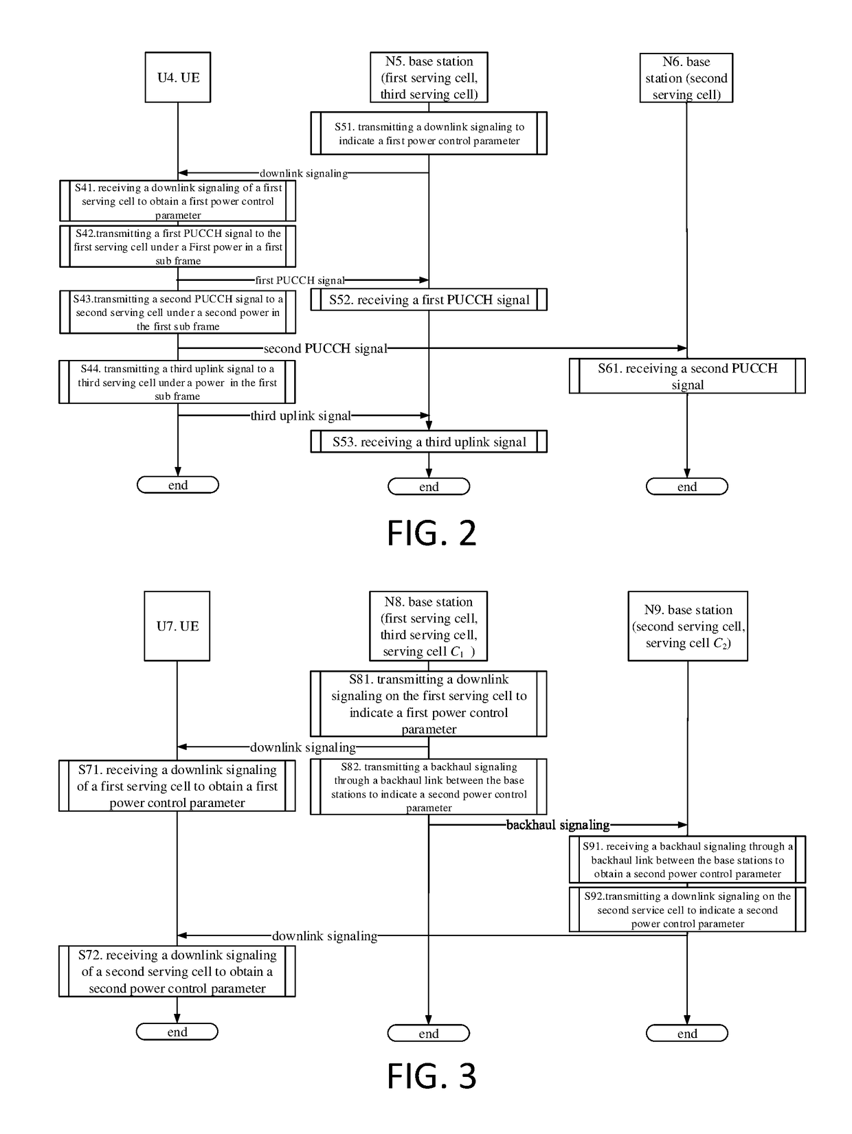
[0096]Embodiment II is a flowchart of transmitting uplink signals on three cells simultaneously, as shown in FIG. 2. In Embodiment II, the base station N5 is a maintaining base station of a first serving cell and a third serving cell, and the base station N5 is a primary base station. The base station N6 is a maintaining base station of a second serving cell, and the base station N6 is a secondary base station.

[0097]For the UE U4, in step S41, the method involves receiving a downlink signaling of a first serving cell to obtain a first power control parameter; in step S42, the method involves transmitting a first PUCCH signal to the first serving cell under a power P1PUCCH in a first sub frame; in step S43, the method involves transmitting a second PUCCH signal to a second serving cell under a power P2PUCCH in the first sub frame; in step S44, the method involves transmitting a third uplink signal to a third serving cell under a power P3PUSCH_UCI in the first sub frame.

[0098]For the ...

embodiment iii

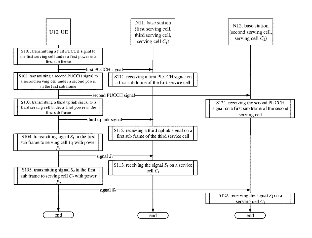
[0104]Embodiment III is a flowchart of transmitting a backhaul signaling to exchange power control parameter through the interface between the base stations, as shown in FIG. 3. In Embodiment III, the base station N8 is a maintaining base station of a first serving cell, a serving cell C1 and a third serving cell, and the base station N8 is a primary base station. The base station N9 is a maintaining base station of a serving cell C2 and a second serving cell, and the base station N6 is a secondary base station.

[0105]For the UE U7, in step S71, the method involves receiving a downlink signaling of a first serving cell to obtain a first power control parameter; in step S72, receiving a downlink signaling of a second serving cell to obtain a second power control parameter.

[0106]For the base station N8, in step S81, the method involves transmitting a downlink signaling on the first serving cell to indicate a first power control parameter; in step S82, the method involves transmitting a...


PUM


Abstract

A method and a device for multiple-serving-cell connectivity in a UE and in a base station are disclosed in the present invention. Addressing the problem of the PUCCH power reduction that can be caused by PUCCH transmission on a secondary cell during dual-connectivity communication, the present invention provides a solution for PUCCH power reduction during dual-connectivity communication. In one embodiment, when power is reduced, the priority of PUCCH transmission on a secondary cell is lower than the priority of PUCCH transmission on a primary cell. The present invention can ensure PUCCH reception quality on a primary cell, guaranteeing the robustness of UE connectivity. Moreover, the present invention maintains the highest degree of compatibility with present systems.

Description

[0001]This application is a U.S. National Phase application under 35 U.S.C. §371 of International Application No. PCT / CN2015 / 072911, filed on Feb. 12, 2015, and claims benefit to Chinese Patent Application No. CN201410052284.9, filed on Feb. 14, 2014, all of which is hereby incorporated by reference for all purposes. The International Application was published in China on Aug. 20, 2015 as WO2015120807 A2 under PCT Article 21 (2).BACKGROUND[0002]Technical Field[0003]The present invention is related to a method and a device for uplink power control in a dual-connectivity communication in the mobile communication technique field, and more particular to a scheme for uplink power control in a scenario of a dual-connectivity communication technique adopted in Long Term Evolution (LTE) system.[0004]Related Art[0005]The Release 12 (R12) version of the 3rd Generation Partner Project (3GPP) introduces an issue of a small cell enhancement (SCE). On the basis of R11 research, a solution scheme ...

Claims


Application Information

Patent Timeline
Patent Type & Authority Patents(United States)
IPC IPC(8): H04W52/02H04W52/32H04W72/04H04W52/14H04L5/00
CPCH04W52/325H04L5/001H04W52/146H04W72/0413H04L5/0048H04L5/0053H04W52/0212Y02B60/50H04W52/14H04W52/265H04W52/36H04B7/024H04W52/16H04W52/367H04W52/40H04W52/34H04W76/15Y02D30/70H04W72/21
Inventor ZHANG, XIAOBO
Owner SISVEL INT
Why Eureka
Try Eureka