Lighting system with a daily rhythm and dim light dynamics

a technology of dim light dynamics and light rhythm, which is applied in the field of light system, can solve the problems of compromising sleep, not always providing the right ambience to unwind and relax, and people (like demented elderly, babies and children) feel uncomfortable, so as to improve sleep quality, improve sleep quality, and improve sleep quality

Active Publication Date: 2017-11-14
SIGNIFY HLDG BV
View PDF11 Cites 4 Cited by
  • Summary
  • Abstract
  • Description
  • Claims
  • Application Information

AI Technical Summary

Benefits of technology

[0004]Light coming in the eye and falling upon a third photoreceptor regulates the biological clock in mammals. The biological clock has a daily rhythm which can be influenced by light. The biological clock regulates our sleep-wake rhythm and impacts well-being. Moreover, dynamic light effects can play an important role in the well-being and sleep-wake regulation of people. The room ambience impacts the stress levels and affective state of the person living in that room. This can have a positive influence on the sleep-wake cycle, when a person becomes less stressed and more relaxed in a pleasant atmosphere while falling asleep or returning to sleep after a nocturnal awakening. Dynamics light effects can be used to activate or unwind people on different moments of the day.

Problems solved by technology

Light at night is known to enhance alertness but also suppresses the melatonin secretion, compromising sleep.
Darkness or dim light can make people (like demented elderly, babies and children) feel uncomfortable, and does not always provide the right ambience to unwind and relax while falling asleep, or when trying to return to sleep.
Darkness or dim light conditions are needed for good and consolidated sleep, but do not always provide an attractive atmosphere / ambience to fall asleep, or quickly return to sleep after nocturnal awakenings.
In many care environments like elderly care-homes pediatric wards, geriatric wards or NICU (neonatal intensive care units) facilities, the sleep of the individuals cared for is not optimal.
The current general lighting systems in care institutions do not allow for light settings that promote a rapid sleep onset.

Method used


Image

  • Lighting system with a daily rhythm and dim light dynamics
  • Lighting system with a daily rhythm and dim light dynamics
  • Lighting system with a daily rhythm and dim light dynamics

Examples


Embodiment Construction

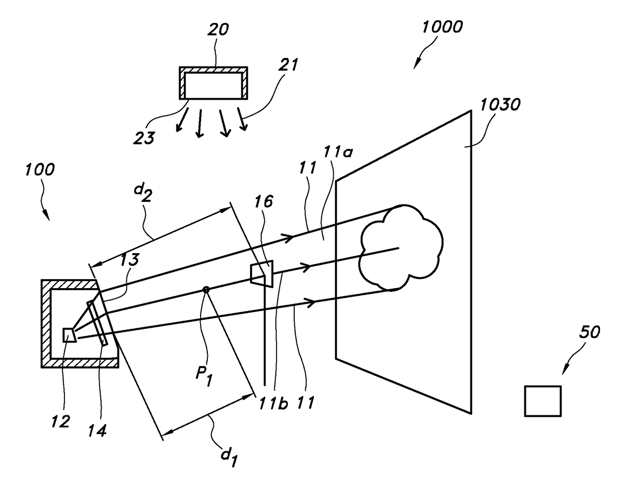
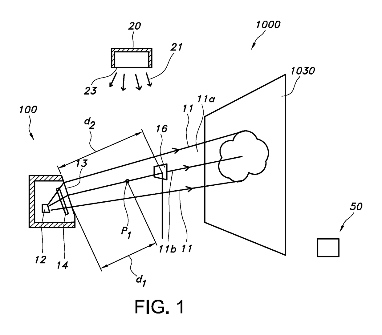
[0088]FIG. 1 schematically depicts a lighting system 100 comprising a first lighting element 10 and a control unit 50. The first lighting element 10 is configured to provide first lighting element light 11 with controllable first lighting element illuminance. A first position p1 is indicated, at which the illuminance may be evaluated. This first position p1 is within a first distance d1 from the lighting element 10, with the first distance 0

[0089]The first lighting element has a light exit window 13. Further, the lighting system may be further configured to provide first lighting element light (11) with a dynamic property selected from the group of a moving or changing light pattern, a color change, and an intensity change. To this end, the lighting element may comprise a plurality of light sources, with reference indicated one or more light sources, and / or a display element, such as a moving element with a transparent (colored) piece or an LCD element. Other options are al...


PUM


Abstract

The invention provides a lighting system (100) comprising a first lighting element (10) and a control unit (50), wherein: a) the first lighting element (10) is configured to provide first lighting element light (11) with controllable lighting intensity, wherein the first lighting intensity can be selected from a plurality of values in the range of 0-I, with I being a predetermined first lighting element maximum intensity; b) the control unit (50) is configured to maintain a first lighting element intensity, during a first predetermined period at an intensity value larger than zero when a general lighting intensity is below a predetermined first threshold level; c) the control unit (50) is further configured to maintain the first lighting element intensity during a second predetermined period at an intensity value a*y*I when the general lighting intensity level is y*I, y being the factor the general lighting intensity is below I, with 0<y<1, the parameter a being a predetermined lighting setting with 0<a≦1 / y; and d) the lighting system is further configured to provide during a third predetermined period first lighting element light (11) with a dynamic property selected from the group of a moving or changing light pattern, a color change, and an intensity change.

Description

CROSS-REFERENCE TO PRIOR APPLICATIONS[0001]This application is the U.S. National Phase application under 35 U.S.C. §371 of International Application No. PCT / EP2014 / 069744, filed on Sep. 17, 2014, which claims the benefit of European Patent Application No. 13185513.2, filed on Sep. 23, 2013. These applications are hereby incorporated by reference herein.FIELD OF THE INVENTION[0002]The invention relates to a lighting system and a method for controlling lighting in a room, for instance with such lighting system. The invention also relates to a computer program product, when run a computer, being configured to control a lighting system according to such method.BACKGROUND OF THE INVENTION[0003]The generation of light cycles is known in the art. U.S. Pat. No. 5,589,741, for instance, describes a naturalistic illumination system for a user at a location having a light source for providing illumination of variable intensity above a non-zero value to the user location. A computer produces a ...

Claims


Application Information

Patent Timeline
Patent Type & Authority Patents(United States)
IPC IPC(8): H05B37/02
CPCH05B37/029H05B47/155A61M21/02A61M2205/587A61M2021/0044A61M2021/0083A61M2205/505A61M2230/63A61M2205/3375A61M2230/005
Inventor SCHLANGEN, LUCAS JOSEF MARIAMEEKES, GABRIELLE JOHANNA BERNARDA MARIABAAIJENS, JOHANNES PETRUS WILHELMUS
Owner SIGNIFY HLDG BV
Why Eureka
Try Eureka