Three column spinal fixation implants and associated surgical methods

a spinal fixation and three-column technology, applied in the field of spinal fixation implants and associated surgical methods, can solve the problems of time-consuming and technical challenges of the anterior approach, and achieve the effects of reducing operative time, improving operative functionality, and improving operative simplicity

Active Publication Date: 2017-11-21
TEPPER GIL +2
View PDF33 Cites 1 Cited by
  • Summary
  • Abstract
  • Description
  • Claims
  • Application Information

AI Technical Summary

Benefits of technology

[0006]In various exemplary embodiments, the present invention allows a surgeon to insert one portion of an implant system with anterior screws from the front, and then connect posterior screws to the anterior screws from the back. This can be accomplished using one unified system and ‘coupling’ portions of the system together from the front and back, thereby creating a true 360 degrees of fixation. In general, it is novel to couple anterior and posterior implant systems to provide three column spinal fixation and stabilizing compression. The present invention provides enhanced operative simplicity and reduced operative time, with superior operative functionality. It is ideally suited for use in the lumbar spine, with the anterior aspect exposed at the operative level. Three column fixation is achieved when the anterior column across the vertebral body is fused and two posterior column fixation points (across the load bearing facet joints) are also fused, such that immobility and stability of the level is achieved, thereby eliminating instability and nerve irritation.
[0008]In another exemplary embodiment, a three column spinal fixation implant, comprises: an anterior cage configured to be disposed in an intervertebral space between adjacent vertebral bodies in a spine of a patient; an anterior plate coupled to the anterior cage; a pair of anterior screws coupled to the anterior cage and the anterior plate and extending posteriorly from the anterior cage and the anterior plate through a portion of one or more of the adjacent vertebral bodies and into or through posterior bony structures of the spine of the patient; a pair of anterior screws coupled to the anterior plate and extending posteriorly from the anterior plate through a portion of one or more of the adjacent vertebral bodies and into or through posterior bony structures of the spine of the patient; a plurality of posterior headbodies coupled to the anterior screws opposite the anterior cage and the anterior plate; and one or more connecting structures coupled to the plurality of posterior headbodies; wherein the three column spinal fixation implant provides structural stability to the spine of the patient across a first anterior column, a second middle column, and a third posterior column thereof.

Problems solved by technology

This posterior approach is time consuming, technically challenging, and, for accuracy, sometimes it is robotically assisted to minimize the risk of nerve injury.

Method used


Image

  • Three column spinal fixation implants and associated surgical methods
  • Three column spinal fixation implants and associated surgical methods
  • Three column spinal fixation implants and associated surgical methods

Examples


Embodiment Construction

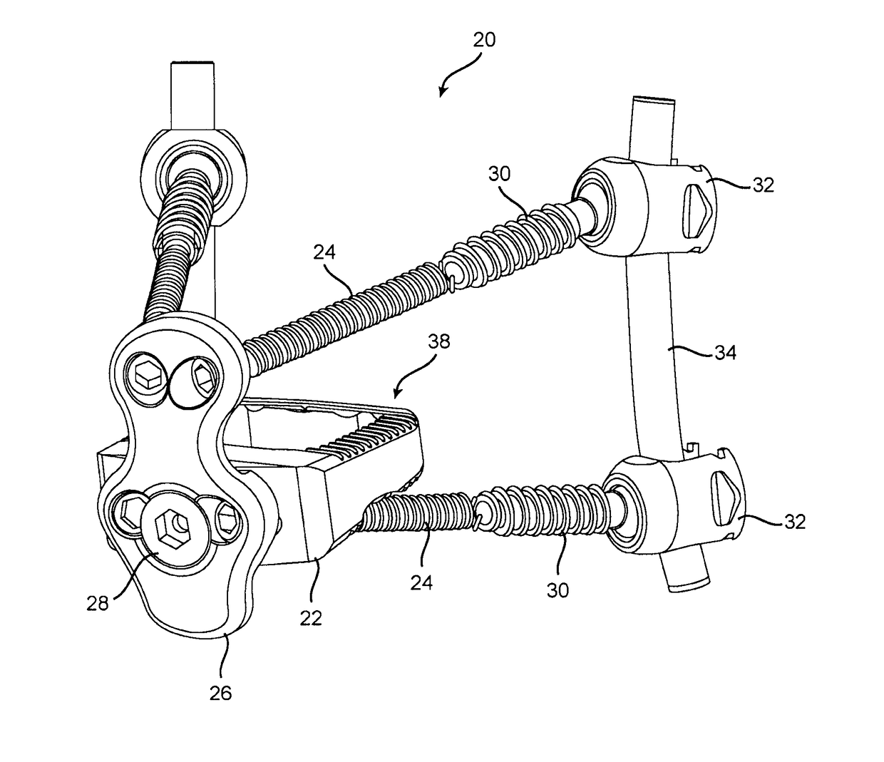
[0037]Again, in various exemplary embodiments, the present invention allows a surgeon to insert one portion of an implant system with anterior screws from the front, and then connect posterior screws to the anterior screws from the back. This can be accomplished using one unified system and ‘coupling’ portions of the system together from the front and back, thereby creating a true 360 degrees of fixation. In general, it is novel to couple anterior and posterior implant systems to provide three column spinal fixation and stabilizing compression. The present invention provides enhanced operative simplicity and reduced operative time, with superior operative functionality.

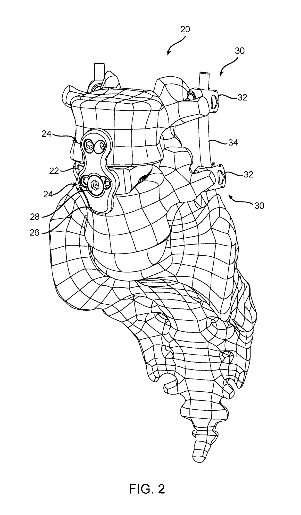
[0038]Referring now specifically to FIGS. 2-4, in one exemplary embodiment, the spinal implant 20 of the present invention includes an anterior cage 22 in the form of an interbody spacer that is disposed in the disc space of a desired segment. A plurality of anterior screws 24 are threaded through the anterior cage 22...


PUM


Abstract

A three column spinal fixation implant, including: an anterior cage configured to be disposed in an intervertebral space between adjacent vertebral bodies in a spine of a patient; an anterior plate coupled to the anterior cage; a pair of anterior screws coupled to the anterior cage and the anterior plate and extending posteriorly from the anterior cage and the anterior plate through a portion of one or more of the adjacent vertebral bodies and into or through posterior bony structures of the spine of the patient; a pair of anterior screws coupled to the anterior plate and extending posteriorly from the anterior plate through a portion of one or more of the adjacent vertebral bodies and into or through posterior bony structures of the spine of the patient; a plurality of posterior headbodies coupled to the anterior screws opposite the anterior cage and the anterior plate; and one or more connecting structures coupled to the plurality of posterior headbodies; wherein the three column spinal fixation implant provides structural stability to the spine of the patient across a first anterior column, a second middle column, and a third posterior column thereof.

Description

CROSS-REFERENCE TO RELATED APPLICATIONS[0001]The present patent application / patent claims the benefit of priority of U.S. Provisional Patent Application No. 62 / 160,754, filed on May 13, 2015, and entitled “THREE COLUMN FIXATED STAND-ALONE SPINAL IMPLANT,” U.S. Provisional Patent Application No. 62 / 166,635, filed on May 26, 2015, and entitled “TARGETING DEVICE AND METHOD FOR THREE COLUMN FIXATED STAND-ALONE SPINAL IMPLANT,” and U.S. Provisional Patent Application No. 62 / 185,751, filed on Jun. 29, 2015, and entitled “THREE COLUMN FIXATION HAVING SCREW COUPLING ABILITY,” the contents of all of which are incorporated in full by reference herein.FIELD OF THE INVENTION[0002]The present invention relates generally to spinal fixation implants and associated surgical methods. More specifically, the present invention relates to three column spinal fixation implants and associated surgical methods operable for simultaneously anteriorly and posteriorly stabilizing a portion of the spine at a gi...

Claims


Application Information

Patent Timeline
Patent Type & Authority Patents(United States)
IPC IPC(8): A61F2/44A61F2/30A61B17/70A61B17/86
CPCA61F2/447A61B17/7032A61B17/7035A61B17/7044A61B17/7059A61B17/8605A61F2/30771A61B17/8685A61F2310/00023A61F2002/3008A61F2002/30433A61F2002/30828A61F2002/448A61F2/4455A61F2002/30331A61F2002/30387A61F2002/30578A61F2002/30593A61F2002/30904
Inventor TEPPER, GILSPITLER, JAMESHARRIS, PETER
Owner TEPPER GIL
Why Eureka
Try Eureka