
Light guide plate and back light unit employing the same
A backlight module and light source technology, applied in optics, nonlinear optics, instruments, etc., can solve problems such as difficulty in controlling the brightness uniformity of the backlight module 1
Patent Information
- Authority / Receiving Office
- CN · China
- Patent Type
- Patents(China)
- Current Assignee / Owner
- Publication Date
- 2008-11-12
- Estimated Expiration
- Not applicable · inactive patent
Smart Images
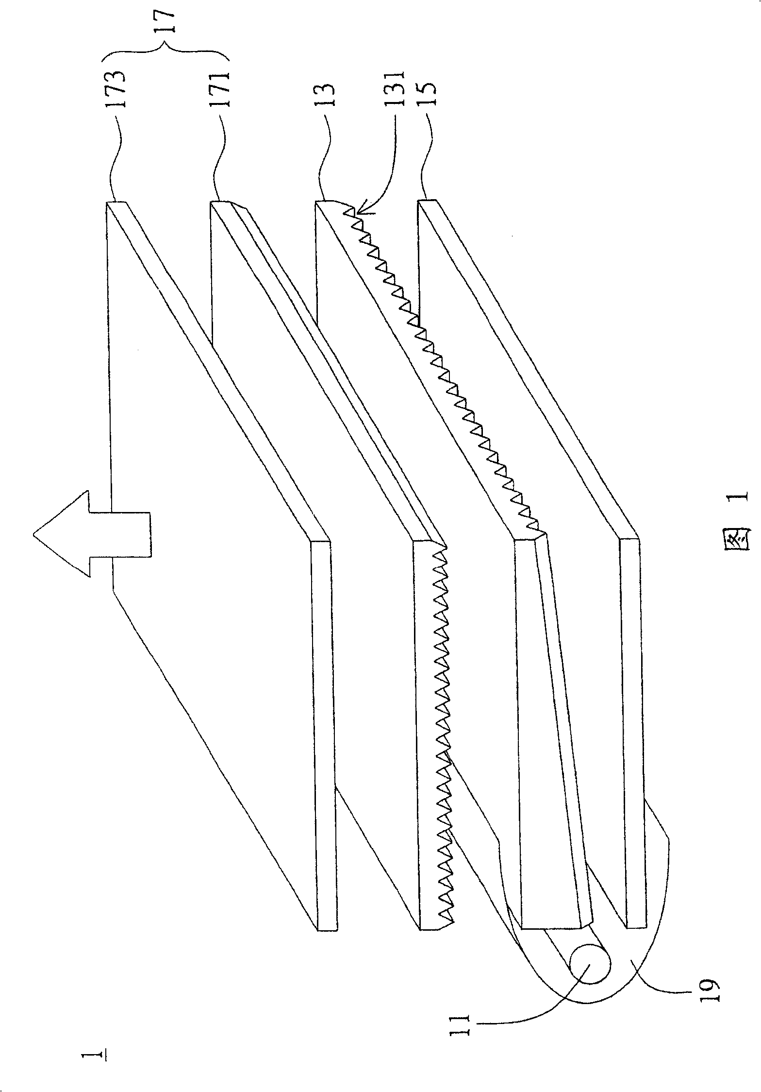
Figure 1 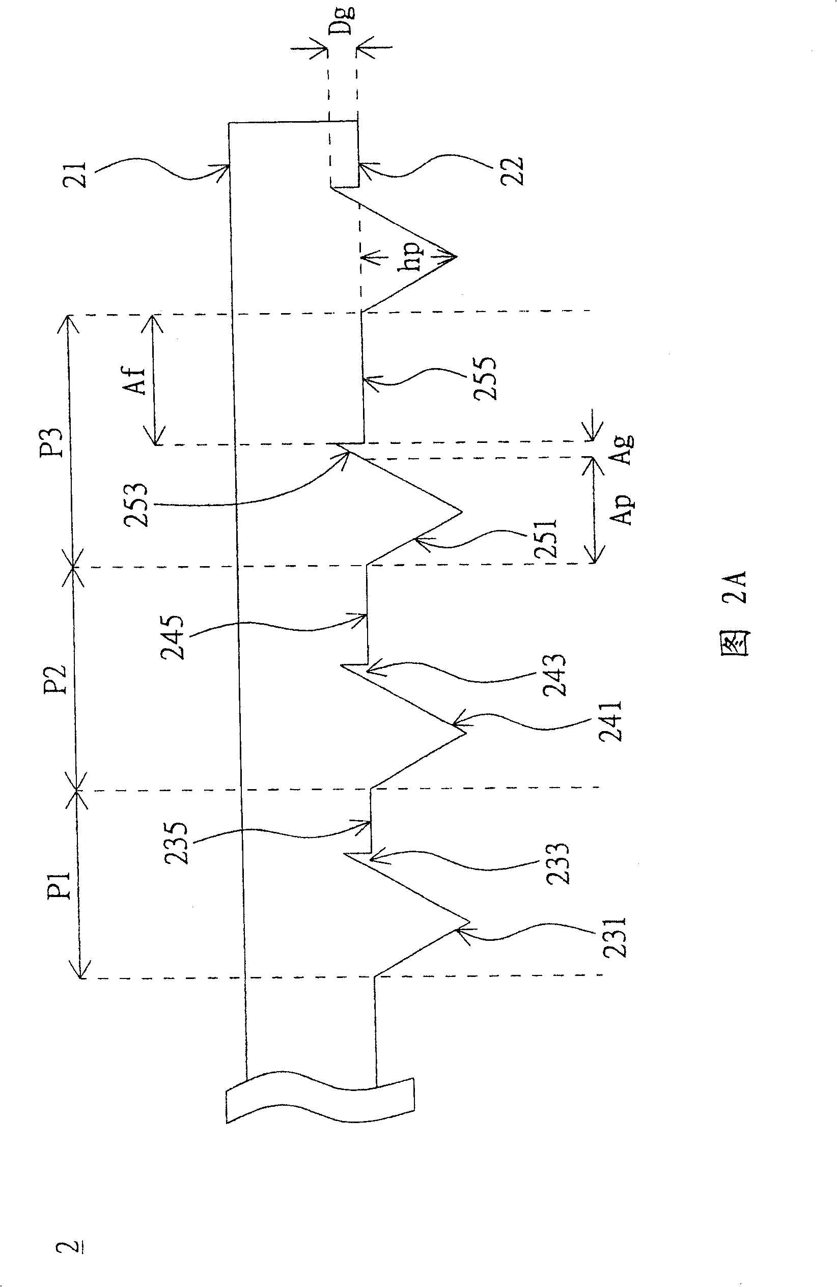
Figure 2 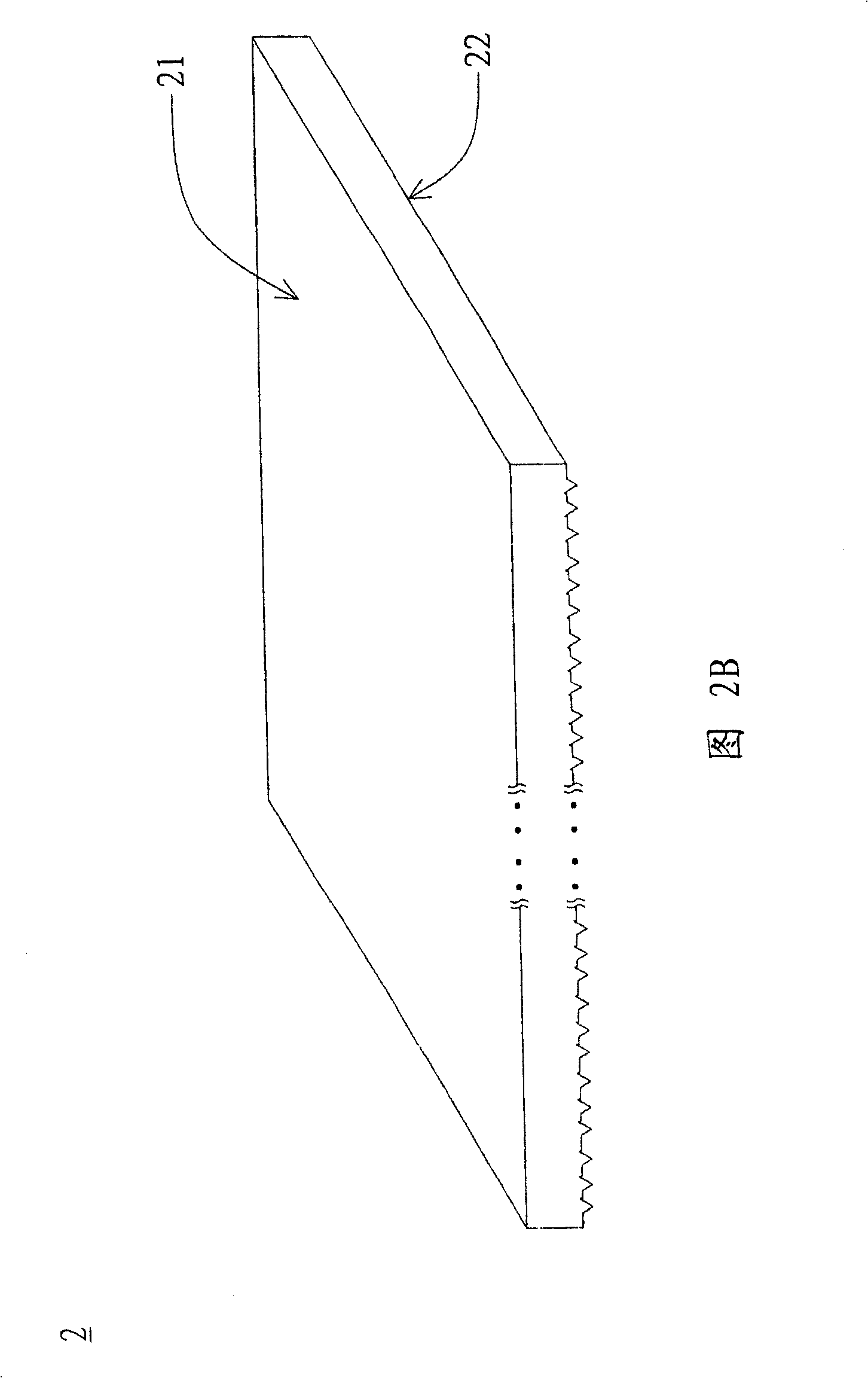
Figure 3
Abstract
Description
technical field
[0001] The present invention relates to a light guide plate and a backlight module applied thereto, in particular to a light guide plate capable of effectively improving the brightness in a small viewing angle range of a liquid crystal display device and a backlight module applied thereto. Background technique
[0002] Liquid crystal display devices that can produce rich and bright graphics are widely used in portable information products such as notebook computers and personal digital assistants due to their thin and light appearance, low power consumption, and no radiation pollution, and are even gradually replacing The cathode ray tube (Cathode Ray Tube, CRT) monitor traditionally used in desktop computers.
[0003] The liquid crystal display device is mainly composed of a display unit, a backlight module and a casing with a frame. The display unit includes a display panel, a circuit board capable of processing data signals, and a supporting thin film pac...
Examples
Embodiment Construction
[0040] The present invention proposes a light guide plate, which is applied to the backlight module of a liquid crystal display device, mainly to form a special optical structure design (or a gradient prism structure design) on the light guide plate to improve the overall optical brightness of the backlight module, especially Optical brightness in a small viewing angle range. The following is a detailed description of the present invention with a preferred embodiment, however, this embodiment will not limit the protection scope of the present invention. In addition, unnecessary elements are omitted in the diagrams to clearly show the technical characteristics of the present invention.
[0041] Please refer to FIG. 2A and FIG. 2B , which illustrate a schematic cross-sectional view and a perspective view of a first-type light guide plate according to a preferred embodiment of the present invention. As shown in FIG. 2A , a light guide plate (LGP) 2 includes a first surface 21 an...