
35KV power distribution station internal and external over voltage monitoring method based on voltage mutual inductor sample
A voltage transformer, 35KV technology, applied in the field of overvoltage online monitoring, can solve the problems of general performance, affecting the safety of measuring equipment and personnel, and high cost, and achieve the effect of saving equipment investment
Patent Information
- Authority / Receiving Office
- CN · China
- Current Assignee / Owner
- Publication Date
- 2009-04-15
- Estimated Expiration
- Not applicable · inactive patent
Smart Images
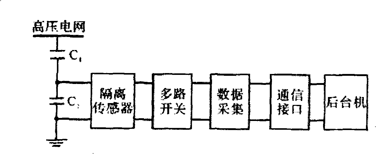
Figure 1 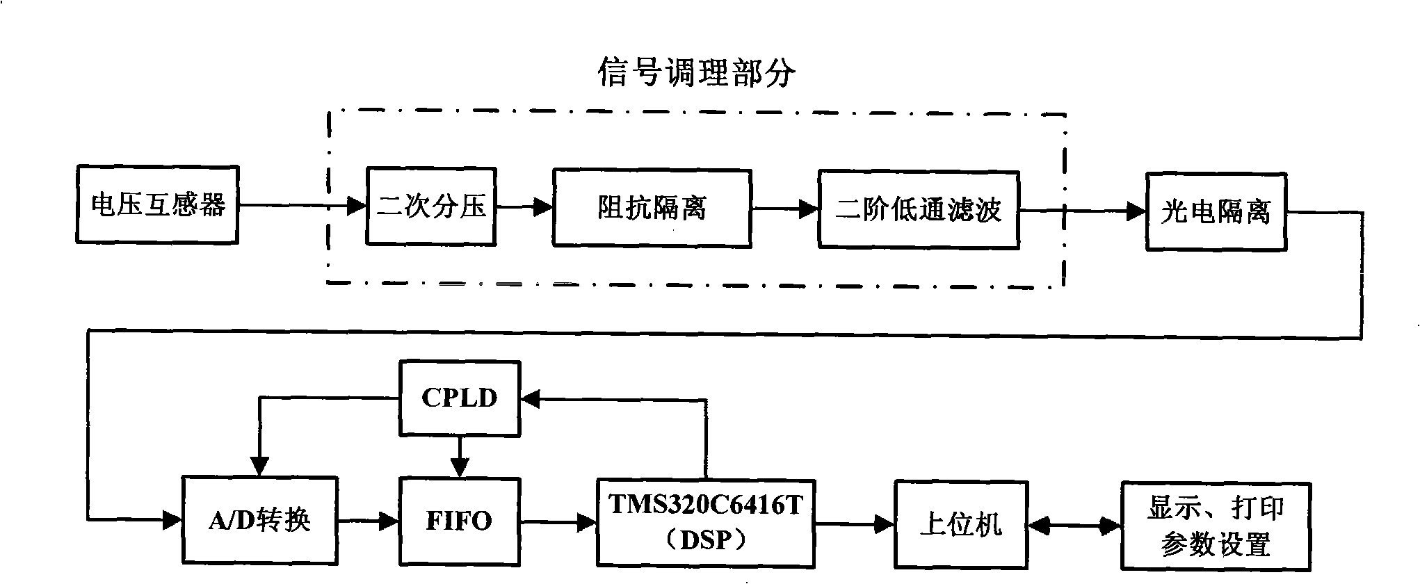
Figure 2 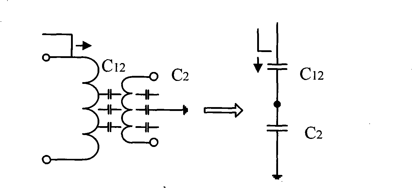
Figure 3
Abstract
Description
technical field
[0001] The invention and a method for monitoring internal and external overvoltages of a 35KV power distribution station based on voltage transformer sampling belong to the online overvoltage monitoring technology. Background technique
[0002] Overvoltage on-line monitoring is the application of on-line monitoring technology in the power field. Acquisition of overvoltage signals is the key to overvoltage on-line monitoring technology. Usually, the equipment that can be used to obtain overvoltage signals includes: voltage transformer, high voltage divider and optical fiber voltage sensor. Among them, high voltage divider is used more often. device to obtain the overvoltage signal. The structural block diagram of a traditional overvoltage monitoring system using a high voltage divider is shown in figure 1 As shown, after the system bus voltage is reduced to an appropriate voltage level by the high-voltage divider, the isolation sensor performs high-speed and...
Examples
Embodiment Construction
[0021] See figure 2 As shown, the present invention is based on the 35KV substation internal and external overvoltage monitoring method of voltage transformer sampling. voltage signal. In the low frequency state, such as power frequency, the steady-state amplitude-frequency response and transient amplitude-frequency response of the voltage transformer are both linear, and they have good overvoltage signal transmission capabilities. The transformer coil will generate electrostatic induction between the coils under the action of impulse voltage such as operating impulse voltage and lightning impulse voltage. At this time, the transmission of voltage is mainly based on electrostatic induction. Compressor to transmit high-frequency impulse voltage signals, such as image 3 As shown, it is a simplified equivalent circuit of the electrostatic induction of the transformer under the high-frequency state of the present invention. It can be seen that it mainly depends on the ground c...