
Method for preparing trimmer
A dresser and abrasive grain technology, which is applied in semiconductor/solid-state device manufacturing, manufacturing tools, metal processing equipment, etc., can solve problems such as shedding, cracks, and easy generation of bubbles in the resin layer, so as to increase the holding force and reduce the bubble content. Effect
Patent Information
- Authority / Receiving Office
- CN · China
- Current Assignee / Owner
- Publication Date
- 2011-06-15
- Estimated Expiration
- Not applicable · inactive patent
Smart Images
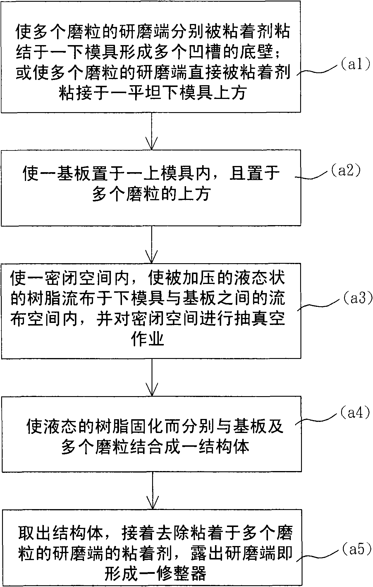
Figure 1 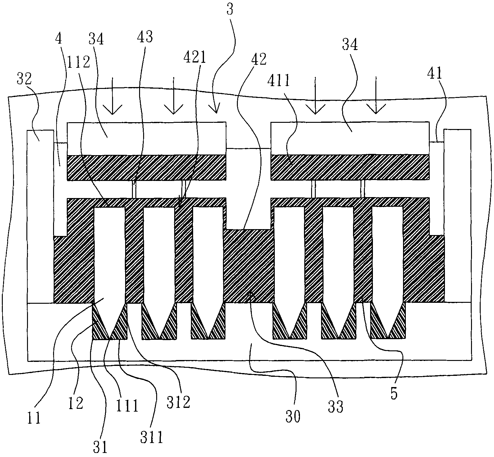
Figure 2 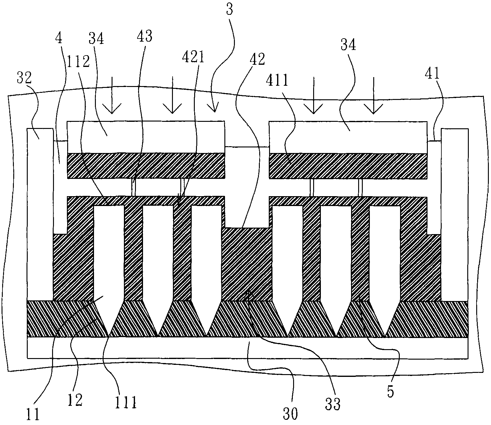
Figure 3
Abstract
Description
technical field
[0001] The present invention relates to implements for conditioning or conditioning chemical mechanical polishing (CMP) pads, and more particularly to methods of making conditioners. Background technique
[0002] Chemical Mechanical Polishing (CMP) is a precision polishing process during wafer production, the purpose is to completely planarize the wafer surface so that the designed micro circuit pattern can be completely distributed on the wafer through the exposure and development process. During chemical mechanical polishing, the abrasive liquid is continuously added to the rotating polishing pad, and the polishing of the wafer surface is completed by means of the mechanical grinding of abrasive grains and the corrosion of chemical oxidants, so that the wafer surface is fully planarized.
[0003] Polishing debris builds up on the surface of the polishing pad during the grinding process. The accumulation will cause the top of the polishing pad to be glazed ...
Examples
Embodiment Construction
[0050] Such as figure 1 , Figure 2-1 , Figure 2-2 , Figure 3-1 , Figure 3-2 , Figure 4 shown. The preparation method of the trimmer according to the first embodiment of the present invention comprises the following steps:
[0051] (a1) The grinding ends 111 of a plurality of abrasive grains 11 are bonded to the bottom wall 311 of a plurality of grooves 31 by the adhesive 12 respectively; 12 bonded above a flat lower mold 30;
[0052] (a2) placing a base plate 4 in an upper mold 32 and placing it above a plurality of abrasive grains 11;
[0053] (a3) In a closed space 3, the pressurized liquid resin 5 is distributed in the distribution space 33 between the lower mold 30 and the substrate 4, and the closed space 3 is vacuumized;
[0054] (a4) solidify the liquid resin 5 and combine with the substrate 4 and the plurality of abrasive grains 11 to form a structure 61 of the first embodiment;
[0055] (a5) Take out the structure 61, such as Figure 3-1 , Figure 3-2A...