
Electroplastic rotary pressing device
A technology of electroplasticity and energization device, applied in the field of electroplastic spinning device, can solve the problems of reducing plastic deformation resistance, poor plasticity, etc., and achieve the effects of reducing plastic deformation resistance, improving efficiency, and low cost and energy loss
Patent Information
- Authority / Receiving Office
- CN · China
- Patent Type
- Patents(China)
- Current Assignee / Owner
- Publication Date
- 2013-12-11
- Estimated Expiration
- Not applicable · inactive patent
Smart Images
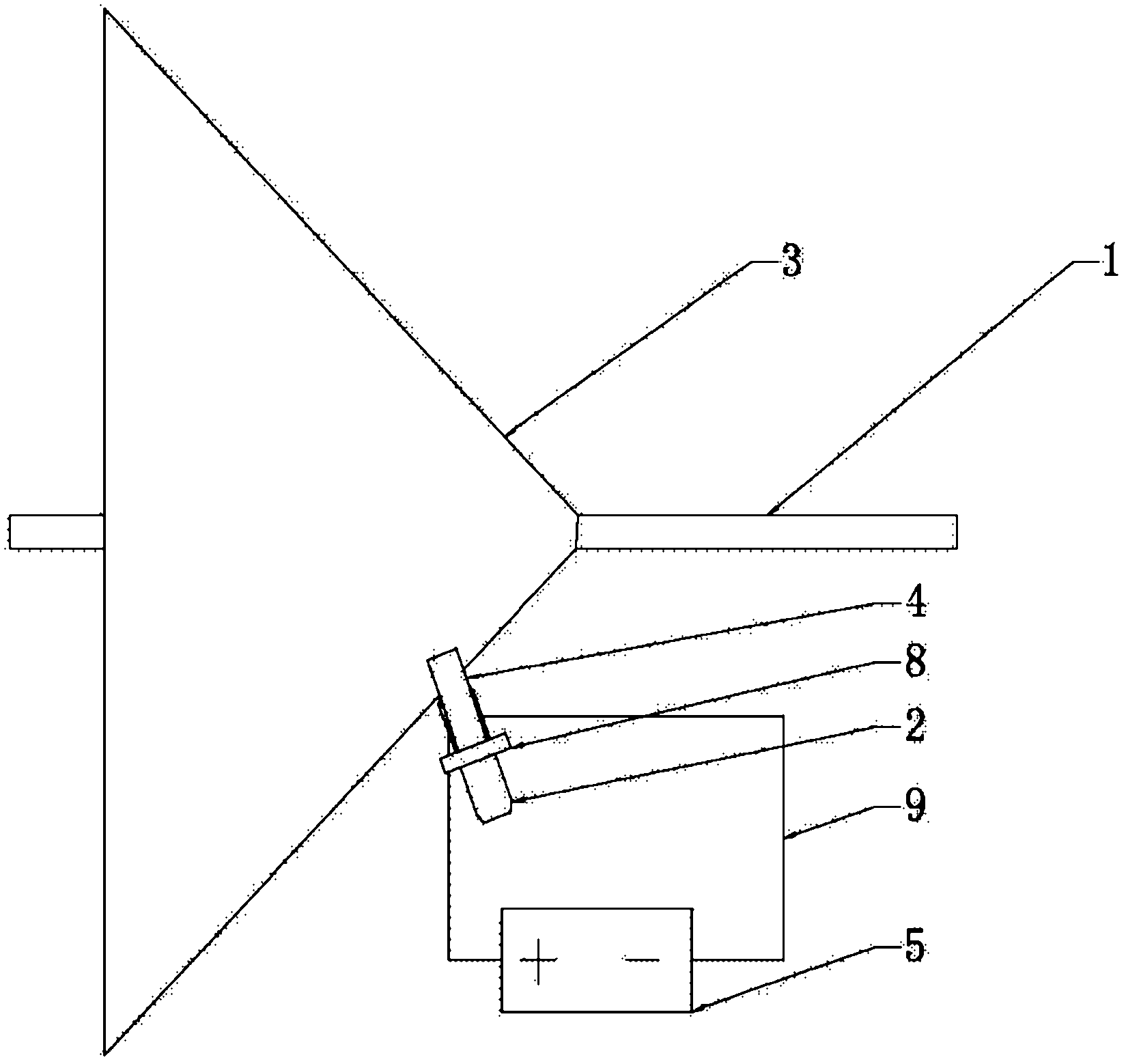
Figure 1 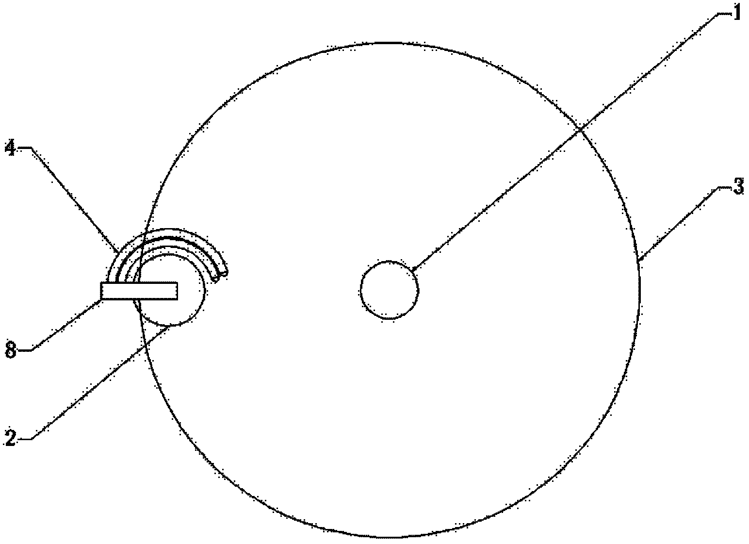
Figure 2 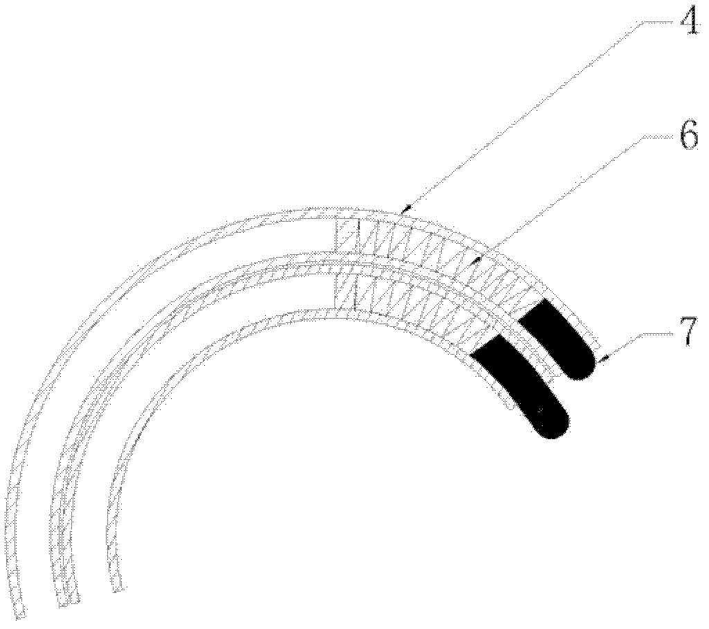
Figure 3
Abstract
Description
technical field
[0001] The invention relates to the technical field of spinning forming in plastic processing, in particular to an electroplastic spinning device. Background technique
[0002] Spinning is an important forming technology in the field of plastic processing. The traditional spinning technology uses the feed motion of tools such as rotary wheels to pressurize the blank that is rotating along the same axis with the spindle of the random machine to produce continuous local plastic deformation, thereby obtaining hollow rotary parts. In order to reduce the increase of deformation resistance caused by work hardening, the existing method is generally to perform heat treatment to ensure the plastic deformation ability of subsequent processing, reduce the deformation resistance, and optimize the structural properties at the same time. However, this method faces some problems, because the nature of some materials determines that they are not suitable for heat treatment....
Examples
Embodiment 1
[0023] Such as figure 1 As shown, this embodiment includes: a main shaft 1, a rotary wheel 2, a blank 3, a power supply 4, a pulse power supply 5, a spring 6, a conductive rod 7, a spinning frame 8 and a wire 9, wherein the external pulse power supply 5 passes through the wire 9 It is connected to the energizing device 4, and the two energizing devices 4 are respectively connected to the positive and negative poles of the pulse power supply 5.
[0024] Such as figure 2 As shown, there are two electrification devices 4, which are distributed on one side of the rotary wheel 2, and are on the same plane as the rotary wheel 2. The devices 4 are all fixed on the wheel frame 8 so that they can move synchronously with the wheel 2 .
[0025] Such as image 3 As shown, the shell of the energizing device 4 is insulated, and there is a conductive rod 7 inside. The head of the conductive rod 7 is hemispherical, so that it can form surface contact with the blank 3 under pressure, and t...
Embodiment 2
[0029] In this implementation example, the blank to be processed is a tungsten-copper refractory alloy, which is circular, with a diameter of 1100mm and a thickness of 1.5mm. The process parameters of the continuous pulse power output pulse current are: peak current 2000A, frequency 300HZ, pulse width 40μs , duty cycle 10%.
[0030] This embodiment is the same as other implementations of Embodiment 1.