
Equipment used for cutting polyvinyl chloride (PVC) pipe
A PVC pipe and equipment technology, applied in metal processing and other directions, can solve the problem of unsatisfactory cutting effect, etc., and achieve the effect of good cutting effect, convenient use and ingenious design
Patent Information
- Authority / Receiving Office
- CN · China
- Current Assignee / Owner
- Publication Date
- 2016-01-13
- Estimated Expiration
- Not applicable · inactive patent
Smart Images
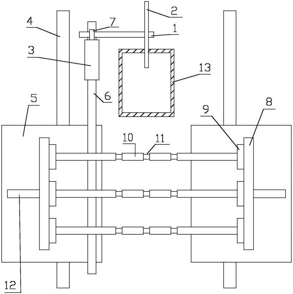
Figure 1
Abstract
Description
technical field
[0001] The invention relates to the technical field of pipe processing equipment, in particular to equipment for cutting PVC pipes. Background technique
[0002] As an important part of chemical building materials, PVC pipes are widely accepted by users for their superior performance, hygiene, environmental protection, and low consumption. In the production process of PVC pipes, it is necessary to cut them according to the length of the required pipes. The cutting effect of the existing equipment is not ideal and needs to be further improved. Contents of the invention
[0003] In order to solve the technical problems existing in the background technology, the present invention proposes a device for cutting PVC pipes with good effect.
[0004] A device for cutting PVC pipes, including a rotating shaft, a saw blade, a driven gear, two brackets, two slide bars, two mounting plates, racks, two clamps, and a drive unit;
[0005] The axis of the rotating shaft ...
Examples
Embodiment Construction
[0023] It should be noted that, in the case of no conflict, the embodiments in the present application and the features in the embodiments can be combined with each other; the present invention will be described in detail below with reference to the accompanying drawings and in combination with the embodiments.
[0024] refer to figure 1 :
[0025] The present invention proposes a kind of equipment for cutting PVC pipes, including a rotating shaft 1, a saw blade 2, a driven gear 3, two brackets, two sliding rods 4, two mounting plates 5, racks 6, and two clamps , a drive unit, N support rods 10, and a collection box 13.
[0026] The axis of the rotating shaft 1 is arranged horizontally, and the rotating shaft 1 is provided with an external gear 7 , the axis of the external gear 7 coincides with the axis of the rotating shaft 1 .
[0027] The saw blade 2 is installed on the rotating shaft 1 , and the axis of the saw blade 2 coincides with the axis of the rotating shaft 1 .
...