
Tool Changing Control Method for Servo Tool Magazine
A control method and tool magazine technology, which is applied in the direction of automatic control devices, manufacturing tools, metal processing machinery parts, etc., can solve the problems of the influence of tool change accuracy and the inability to increase the tool change rate of servo tool magazine, so as to improve machining accuracy, The effect of avoiding impact and increasing speed
Patent Information
- Authority / Receiving Office
- CN · China
- Patent Type
- Patents(China)
- Current Assignee / Owner
- Publication Date
- 2018-10-19
Smart Images
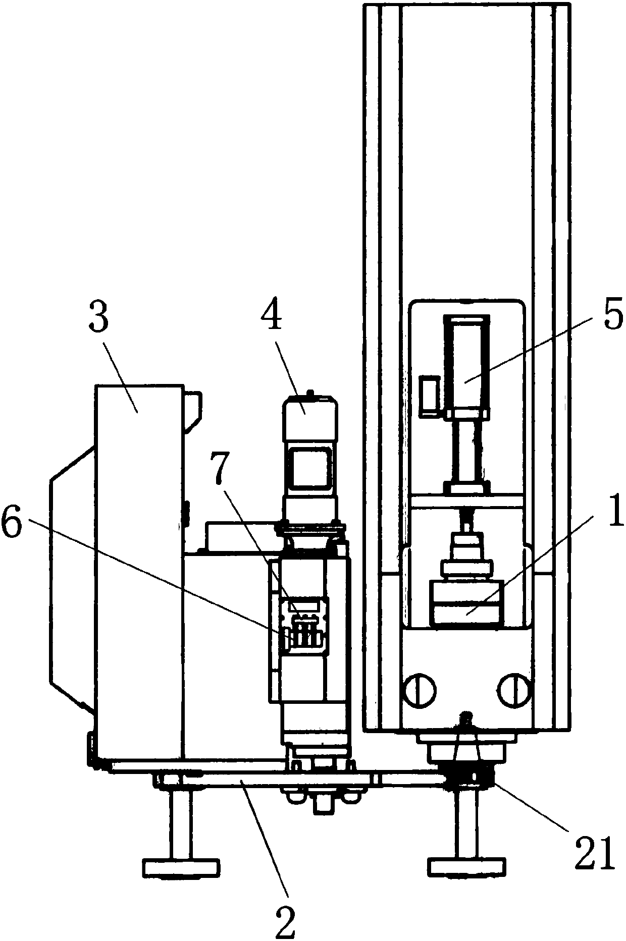
Figure 1
Abstract
Description
technical field
[0001] The invention relates to a tool change control method of a servo tool magazine. Background technique
[0002] In the process of CNC machine tool processing, in order to improve the productivity of the machine tool, it is effective to shorten the tool change time of the tool. In order to shorten the tool change time, it is better for the machine tool to complete the movement of the tool for the next process before ending the processing of the current process. The tool change action of the existing tool magazine is one step after another. When some steps are in place, it is necessary to wait for the end of the next step before starting the next action. Therefore, the tool change efficiency is not very high.
[0003] In addition, the multiple tools accommodated in the tool magazine are used for different processing. Therefore, the weight of each tool is varied. When a heavier tool is moved and changed, the kinetic energy of the moving object is greater...
Examples
Embodiment Construction
[0026] The present invention is described in further detail now in conjunction with accompanying drawing. These drawings are all simplified schematic diagrams, which only illustrate the basic structure of the present invention in a schematic manner, so they only show the configurations related to the present invention.
[0027] A tool change control method for a servo tool magazine, used for tool change on spindle 1, such as figure 1 As shown, a knife arm 2 is provided on one side of the main shaft 1, and a tool magazine 3 is provided on one side of the knife arm 2. Part 21, the knife arm 2 is driven to rotate by the servo drive motor 4, a tool is connected to the main shaft 1 and the knife is punched or pulled by the knife punching cylinder 5; the servo tool magazine tool change control method includes the following steps:
[0028] Knife buckle: The servo drive motor 4 rotates the knife arm 2 to the first position according to the set length of the knife buckle pulse, so tha...