
Range hood
A range hood and oil fume technology, which is applied in the field of kitchen appliances, can solve the problems of large wind resistance, the smooth airflow of the rotating filter screen cannot be fully reflected, and the short path, etc., to achieve a large negative pressure gradient, improve the effect of the range hood, small size effect
Patent Information
- Authority / Receiving Office
- CN · China
- Patent Type
- Applications(China)
- Current Assignee / Owner
- Publication Date
- 2019-04-09
Smart Images
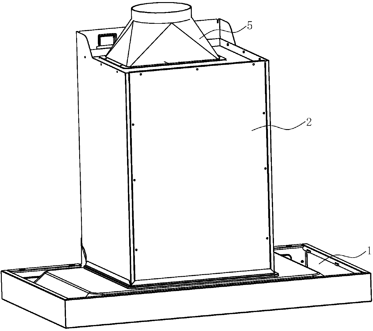
Figure 1 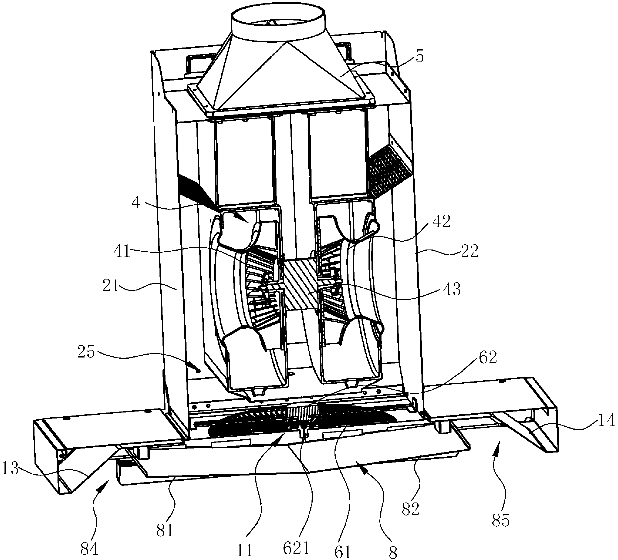
Figure 2 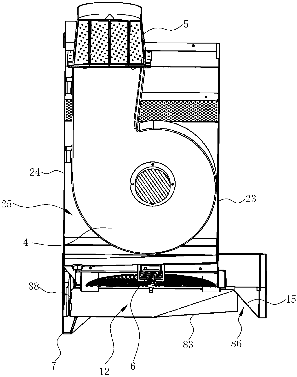
Figure 3
Abstract
Description
technical field
[0001] The invention relates to kitchen appliances, in particular to a range hood. Background technique
[0002] Range hoods have become one of the indispensable kitchen appliances in modern families. Generally, range hoods include top-suction and near-suction types. Top-suction range hoods use the principle of rising hot air to absorb and discharge the naturally rising oil fumes generated during cooking. It has more and more widespread applications.
[0003] Existing range hoods are equipped with filter screens for the purpose of collecting cooking fumes, dust, and the like. For example, a range hood disclosed in a Chinese patent with application number 200780027956.9 has a hood with an air duct, an exhaust fan located in the air duct, a filter screen located in the air duct and in front of the exhaust fan, and the driving part is connected to On the filter screen, a flat rectifying plate is arranged near the suction port in the hood; another example is a...
Examples
Embodiment 1
[0034] see Figure 1 ~ Figure 4, a range hood, comprising a smoke collection hood 1, a chassis 2 arranged above the fume collection hood 1, a fan system 4 is arranged in the chassis 2. An air inlet 11 is provided on the fume collecting hood 1, so that the fan system 4 in the cabinet 2 can suck oily fume into the cabinet 2 through the air inlet 11 and discharge it to the public flue.
[0035] The cabinet 2 includes a left side wall 21, a right side wall 22, a front side wall 23, and a rear side wall 24. The cavity between the above-mentioned side walls forms an air duct 25 for the oil fume flow. Preferably, the air duct 25 gradually moves from bottom to top. zoom out.
[0036] In this embodiment, the blower system 4 is a three-way blower, and the three-way blower can adopt the existing technology, as disclosed in the Chinese patent application number 201310418009.X. The fan system 4 can be a single ternary fan, two parallel ternary fans or two series ternary fans. Since the t...
Embodiment 2
[0060] see Figure 9 and Figure 10 , in this embodiment, the difference from the first embodiment above is that the first ternary fan system 41 and the second ternary fan system 42 share the same volute 44, that is, the first ternary fan system 41 of the first ternary fan system 41 The first three-way impeller 412 and the second three-way impeller 422 of the second three-way blower system 42 are both arranged in the same volute 44 .
[0061] A mounting plate 45 is arranged between the two ternary impellers, thereby separating the two ternary impellers on both sides of the mounting plate 45, and the mounting plate 45 extends to the top of the volute 44, thereby dividing the volute 44 into two The first oil fume passage 441 and the second oil fume passage 442 are independent. The driving motor 43 passes through the mounting plate 45 and is connected and fixed with the mounting plate 45 .
[0062] In this embodiment, the air outlet cover 5 only includes a cover body 51 and a ...