
Angle steel flange machine for fence
A steel flange machine and guardrail technology, applied in the direction of non-rotational vibration suppression, can solve problems such as unreasonable structural design, and achieve the effects of simple and reasonable structural design, prevention of displacement, and fewer failures
Patent Information
- Authority / Receiving Office
- CN · China
- Patent Type
- Applications(China)
- Current Assignee / Owner
- Publication Date
- 2020-03-03
- Estimated Expiration
- Not applicable · inactive patent
Smart Images
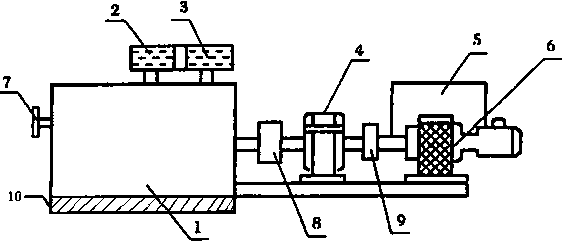
Figure 1
Abstract
Description
technical field
[0001] The invention relates to the technical field of guardrail equipment, in particular to an angle steel flange machine for guardrails. Background technique
[0002] Angle steel flange machine is widely used in fan, bridge formwork, chemical equipment, cable rack, mining explosion-proof switch, centrifuge, guardrail and other mechanical equipment industries, and is also suitable for external processing. The existing guardrail uses angle steel flange Machine structure design is unreasonable, therefore urgently need those skilled in the art to design a kind of novel angle steel flange machine for guardrail. Contents of the invention
[0003] The problem to be solved by the present invention is to provide a mechanical machine with high efficiency, few failures, long service life, reliable and stable operation, low noise, convenient disassembly and assembly, easy maintenance, strong bearing capacity, low energy consumption and good economy; The bottom of th...
Examples
Embodiment Construction
[0011] The present invention will be further explained below in conjunction with the accompanying drawings and embodiments.
[0012] Such as figure 1 As shown, an angle steel flange machine for a guardrail includes a machine base 1, a dynamic pressure wheel 2, a fixed pressure wheel 3, a reducer 4, a speed regulating motor 6, a primary coupling 8, and a secondary coupling 9, One end of the base 1 is equipped with a dynamic pressure wheel 2, the upper end of the base 1 is equipped with a dynamic pressure wheel 2, one side of the dynamic pressure wheel 2 is equipped with a fixed pressure wheel 3, and the dynamic pressure wheel 2 It is connected with the constant pressure wheel 3 through transmission, the bottom end of the machine base 1 is bonded with a buffer anti-skid layer 10, and the other end of the machine base 1 is equipped with a first-level coupling 8, and the first-level coupling 8 is connected with the reducer 4. transmission connection, one end of the reducer 4 is e...