
A kind of automatic concrete curing system and curing method
A curing system and concrete technology, applied in the processing of building materials, construction, building structure, etc., can solve the problems of insufficient spray surface, untimely spraying of health solution, and penetration of cracks, etc., to improve the maintenance effect and avoid pipeline layout interference. Effect
Patent Information
- Authority / Receiving Office
- CN · China
- Patent Type
- Patents(China)
- Current Assignee / Owner
- Publication Date
- 2021-11-02
Smart Images
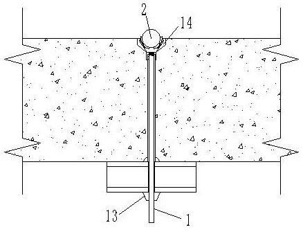
Figure 1 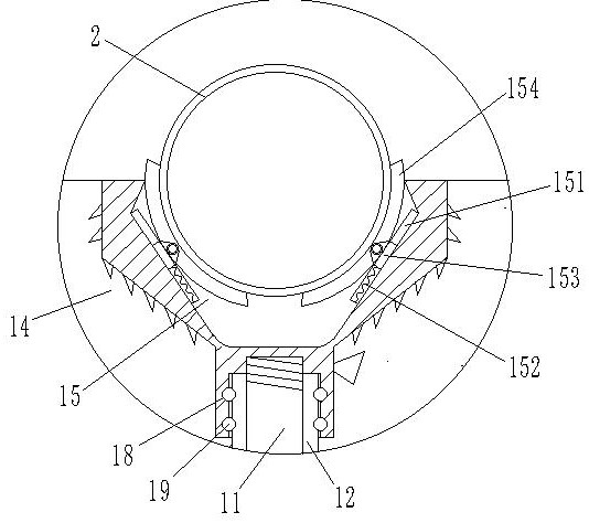
Figure 2 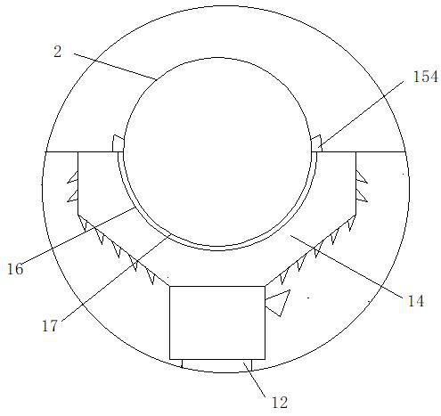
Figure 3
Abstract
Description
technical field
[0001] The invention belongs to the field of cast-in-place concrete maintenance, and in particular relates to an automatic concrete maintenance system and a maintenance method. Background technique
[0002] In the contemporary era of rapid economic development, concrete cast-in-place structures are widely used in the field of construction engineering. ) is not sprayed in time and the spraying area is insufficient, resulting in cracks on the concrete surface (that is, surface cracks). If the maintenance measures are not corrected in time, the surface cracks will eventually develop into deep cracks, and even form through cracks, seriously affecting the safety of concrete structures. and appearance quality. If the pre-buried pipes in the concrete are sprayed to achieve a certain maintenance effect, but the space of the later pipes occupies the space of the later pipeline arrangement, and the possibility of water leakage in the later stage is relatively high, ho...
Examples
Embodiment 1
[0034] refer to Figure 1 to Figure 6 As shown, an automatic concrete maintenance system includes a control body 1, a pre-embedded pipeline 2, a standpipe 3, a sprinkler head 6, a gate valve 4 and a timing automatic opening and closing device 5, and the control body 1 is installed on a structural plate and It is detachably connected with the embedded pipeline 2, and the plane where the horizontal diameter of the embedded pipeline 2 is located is consistent with the design height of the floor concrete. The embedded pipeline 2 and the riser 3 are detachably connected and communicated through threads. The head 6 is detachably connected and communicated with the riser 3 through threads. The gate valve 4 and the timing automatic opening and closing device 5 are installed at the water inlet port of the embedded pipeline 2 . The timing automatic opening and closing device 5 is located outside the gate valve 4 . Utilizing the function of the timing automatic opening and closing device...
Embodiment 2
[0042] A maintenance method for an automated concrete maintenance system, comprising the following steps:
[0043] A. After the installation of the structural plate and the binding of the floor steel bars are completed, the main body rod 11 and the sleeve 12 are installed on the structural plate through the water stop bolt 13, and the bearing body 14 is installed on the top of the main body rod 11 and connected with the top of the sleeve 12. sealed connection;
[0044] B. Push the positioning claw 154 upward, and place the embedded pipeline 2 between the two positioning claws 154, the slider 153 drives the positioning claw 154 to move downward under the action of the reset member 152 and hug the embedded pipeline 2 tightly, Ensure that the plane where the horizontal diameter of the embedded pipeline 2 is located is consistent with the design height of the floor concrete;
[0045] C. Install the standpipe 3 on the pre-embedded pipeline 2, and use a common blocking piece to blo...