
Building construction safety elevator
A technology for building construction and elevators, applied in elevators, elevators in buildings, mechanical equipment, etc., can solve the problems of high use frequency of elevators, affecting the use of elevator boxes, broken teeth of gears, etc., and achieve the effect of reducing impact force.
Patent Information
- Authority / Receiving Office
- CN · China
- Patent Type
- Applications(China)
- Current Assignee / Owner
- Publication Date
- 2021-02-19
- Estimated Expiration
- Not applicable · inactive patent
Smart Images
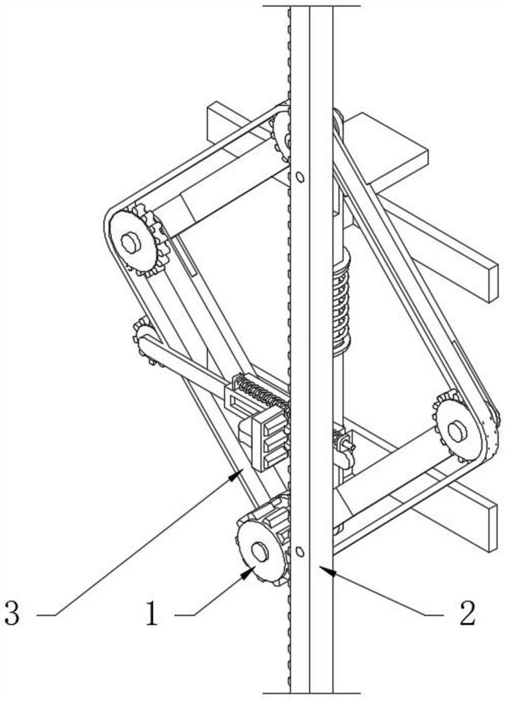
Figure 1 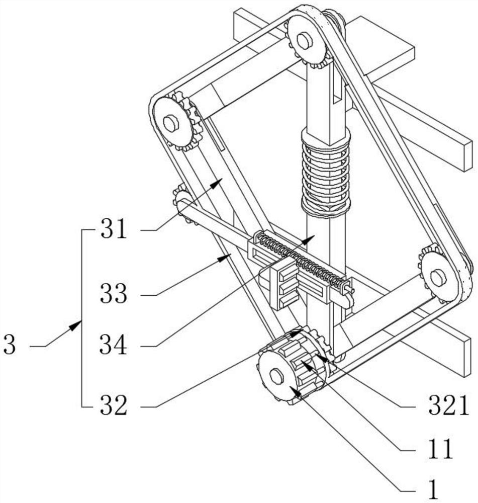
Figure 2 
Figure 3
Abstract
Description
technical field
[0001] The invention relates to the technical field of elevators for building construction, in particular to a safety elevator for building construction. Background technique
[0002] The construction elevator, also known as the construction elevator for construction, is a construction machine often used in construction for carrying people and goods. The current elevator adopts rack and pinion transmission, and a steel structure derrick is built outside the building. The rack is fixed on the frame, and the elevator drives the reducer through the motor. Drive the gear to rotate, the gear and the rack mesh, and then passively realize the up and down movement of the lifting box.
[0003] However, due to the high frequency of use of the lift and the heavy load of the lift box, in order to increase the power input of the lift box, the gears are small in size, which is prone to broken teeth, which directly affects the use of the lift box. In the case of continuous...
Examples
Embodiment 1
[0030] see Figure 1-3 , a building construction safety elevator, including a gear 1 and a rack 2 meshed with the gear 1. This embodiment is created on the basis of the existing gear 1 and the rack 2 meshing to realize lifting; it also includes a driving buffer chain Combination 3, the drive buffer chain combination 3 is the inventive structure of this embodiment, which can effectively solve the problem of broken teeth of the gear 1 and prolong the service life of the gear 1, and can also reduce the impact load of the drive input mechanism; the details are as follows The drive buffer chain combination 3 comprises a parallel hinge four-bar mechanism 31, a main sprocket wheel 32, a chain 33 and a spring damping rod 34, and the parallel hinge four-bar mechanism 31 is composed of four connecting rods with the same length. Rod 34 is positioned at parallel hinge four-bar mechanism 31 and is vertical distribution, and the two ends of this spring damping lever 34 are correspondingly c...
Embodiment 2
[0032] see Figure 4The difference from Embodiment 1 is that an elastic anti-drop condensation mechanism 5 is provided on the side of the lower sleeve 343 close to the rack 2, one end of the elastic anti-fall condensation mechanism 5 is engaged with the chain 33 and the other end is used in conjunction with the rack 2, The effect of this elastic anti-fall condensation mechanism 5 is that after the chain 33 in the embodiment 1 is accidentally disconnected, one end of the elastic anti-fall condensation mechanism 5 is instantly engaged with the rack 2. At this time, the lower casing 343 is fixed relative to the rack 2, and then It has anti-fall effect; specifically, the elastic anti-fall condensation mechanism 5 includes a rectangular guide sleeve 51, a guide plate 52, a return spring 53, a locking plate 54 and a traction sprocket 55, and the guide plate 52 is set on the rectangular guide sleeve 51 throughout. The traction sprocket 55 is rotatably connected to one end of the guid...