
Circuit for harmonizing read and wright between central processor and input output interface device
A central processing unit, input and output technology, applied in the direction of electrical digital data processing, instruments, etc., can solve the problems of reading or writing data errors, too late to send waiting signals, and impracticality, so as to avoid transmission errors and reduce The effect of system design
Patent Information
- Authority / Receiving Office
- CN · China
- Patent Type
- Applications(China)
- Current Assignee / Owner
- Publication Date
- 2003-07-02
- Estimated Expiration
- Not applicable · inactive patent
Smart Images
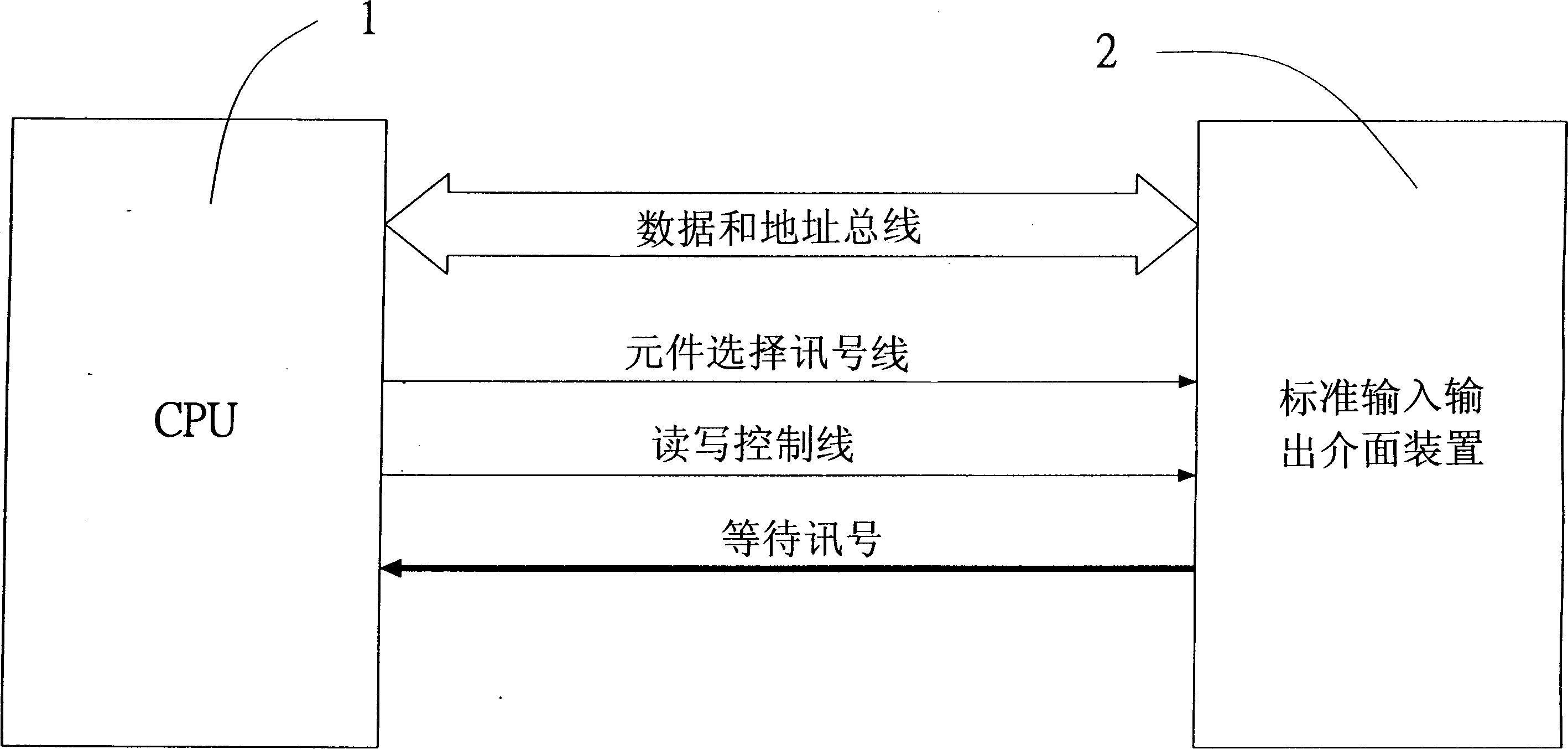
Figure 1 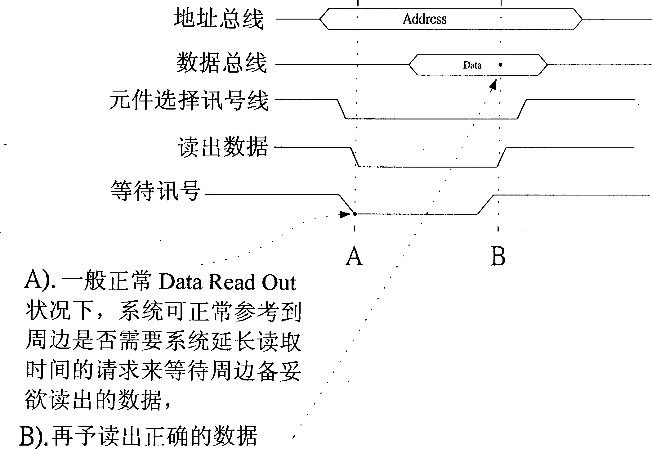
Figure 2 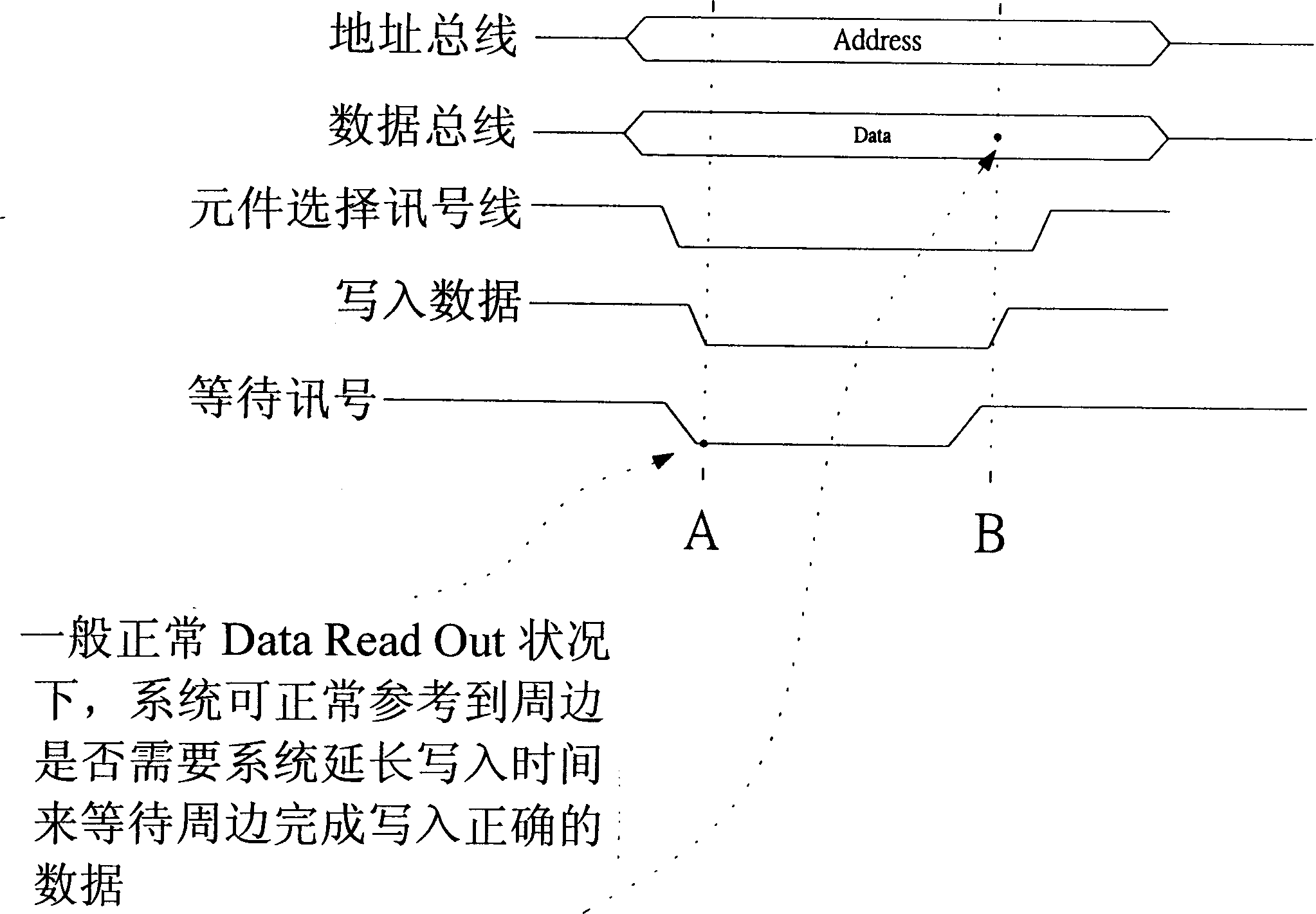
Figure 3
Abstract
Description
technical field
[0001] The invention relates to a computer circuit, in particular to a circuit for coordinating reading and writing between a central processing unit and an input and output interface device. Background technique
[0002] figure 1 What is shown is an example of data transmission between a general CPU (central processing unit) 1 and a PCMCIA Card (standard input and output interface device).
[0003] Wherein when the CPU (central processing unit) 1 transmits data to the peripheral equipment, the PCMCIA Card (standard input and output interface device) addresses and assembles the data through the DATA BUS (data bus) and ADDRESS BUS (address bus), and through The Chip Select (component selection signal line), READ / WRITE (read-write control line) and WAIT (wait signal) lines of the CONTROL BUS (control bus) are used to control the direction of data transmission and whether to open or not. When the peripheral equipment is not ready When the PCMCIA Card (standard...
Examples
Embodiment Construction
[0039] see Figure 6 Shown, the present invention is to set up a synchronous control unit 3 and a signal input unit 5 (referring to Fig. 7, shown in 8) between CPU (central processing unit) 1 and PCMCIA Card (standard input and output interface device) 2, wherein the The synchronous control unit 3 may include:
[0040] A flip-flop 31, the input terminal is connected to the output terminal of a read-write signal extractor 32, and the reverse output terminal is connected to one input terminal of the first comparison logic gate 33, and the input terminal is controlled by the trigger terminal. When the connected CPU (Central Processing Unit) 1 is input with timing pulse (Clock) 4, the reverse output terminal can provide a reverse sync pulse state.
[0041]A read-write signal picker 32, the input end is respectively connected with the signal control lines of the read end (READ) and the write end (WRITE), and the output end is connected to the input end of a flip-flop 31, when Whe...