
Fixing apparatus having a power supply member including first and second members with different linear expansion coefficients, and image forming apparatus
a technology of linear expansion coefficient and fixing apparatus, which is applied in the direction of electrographic process apparatus, instruments, optics, etc., can solve the problems of increasing the power supply member to be detached, and the thermal stress of the power supply member to be repeated, so as to increase the print speed, maintain thermal energy, and increase the temperature of the heater
Patent Information
- Authority / Receiving Office
- US · United States
- Patent Type
- Patents(United States)
- Current Assignee / Owner
- Publication Date
- 2022-07-26
Smart Images

Figure 1 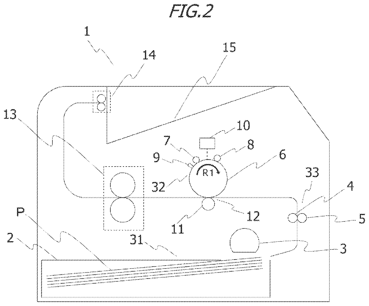
Figure 2 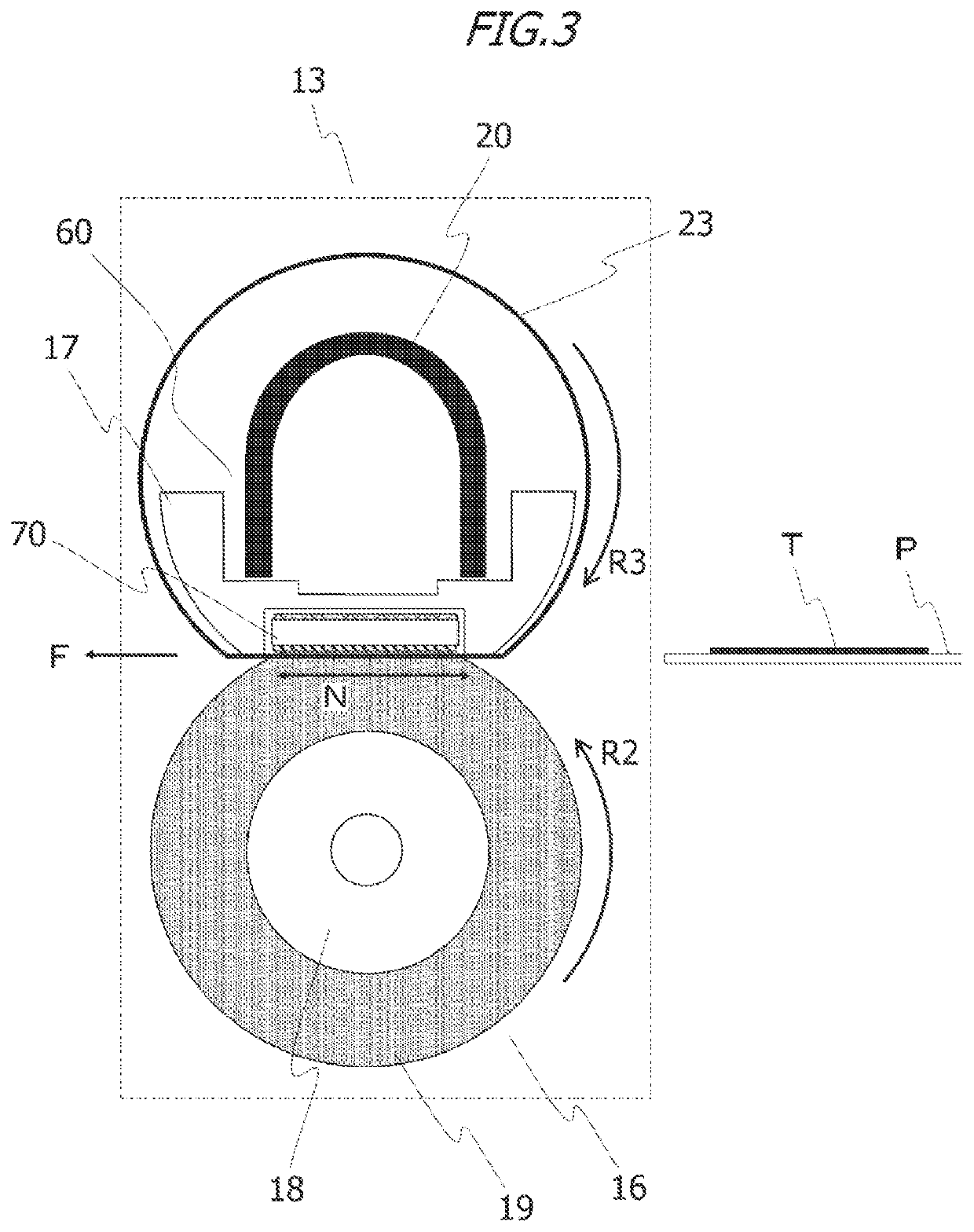
Figure 3
Abstract
Description
BACKGROUND OF THE INVENTIONField of the Invention
[0001] The present invention relates to a fixing apparatus in an image forming apparatus such as a printer or a copying machine.Description of the Related Art
[0002] Image fixing apparatus employing a film heating method, excellent in on-demand property have been widely used as an image fixing apparatus included in an image forming apparatus such as a copying machine or a laser beam printer. Such an image fixing apparatus employing the film heating method includes a heater that serves as a heating source, a supporting member that supports the heater, a heat-resistant heating film, and a pressure roller (pressure member). The heater supported by the supporting member and the pressure roller form a nip portion that sandwiches the heating film. While a recording material is nipped and conveyed by the nip portion formed with the pressure roller and the heating film, an unfixed toner image on the recording material is heated and fixed. The he...
Examples
embodiment 1
[0023
1. Overall Configuration of Image Forming Apparatus
[0024]First, an overall configuration of an image forming apparatus according to the present embodiment will be described with reference to FIG, 2FIG. 2 is a schematic cross-sectional view of an image forming apparatus 1 including an image fixing apparatus 13. The image forming apparatus 1 used in the present embodiment is a laser beam printer employing an electrophotographic method.
[0025]The image forming apparatus 1 includes a recording material feeding portion 31 that feeds a recording material P and an image forming portion 32 that forms an image on the recording material P. In the recording material feeding portion 31, the recording materials P loaded in a cassette 2 are picked up one by one from the topmost recording material P by a sheet feeding roller 3 and conveyed to a registration portion 33. The registration portion 33 includes a registration roller 4 and a registration roller 5. After being aligned in a conveying d...
embodiment 2
[0070
[0071]Next, a configuration of a power supply unit of Embodiment 2 will be described. Components with like configurations and functions as those of Embodiment 1 are denoted by like reference characters, and descriptions thereof will be omitted. A configuration of a heater 70 of Embodiment 2 is the same as that of Embodiment 1 and is as illustrated in FIGS. 5A to 5E.
[0072]In the present embodiment, the configuration of the power supply unit of Embodiment 1 is applied to power supply electrodes 76f to 76i. FIGS. 9A and 9B are perspective views illustrating an example of the power supply unit. FIGS. 9A and 9B illustrate a configuration of the power supply electrodes 76f and 76g in Embodiment 2. A configuration of the power supply electrodes 76h and 76i is the same as that of the power supply electrodes 76f and 76g, and descriptions thereof will thus be omitted. As illustrated in FIG. 9A, a power supply member 100 is positioned by a heater holder 17. As for a fixing method, the pow...