
Common rail for diesel engines
a diesel engine and common rail technology, applied in the direction of fuel injection apparatus, charge feed system, metal-working apparatus, etc., can solve the problems of applying auto-frettage, achieve excellent durability, increase the fatigue strength of inner pressure, and high compressive residual stress
Patent Information
- Authority / Receiving Office
- US · United States
- Patent Type
- Applications(United States)
- Current Assignee / Owner
- Publication Date
- 2006-11-23
- Estimated Expiration
- Not applicable · inactive patent
Smart Images
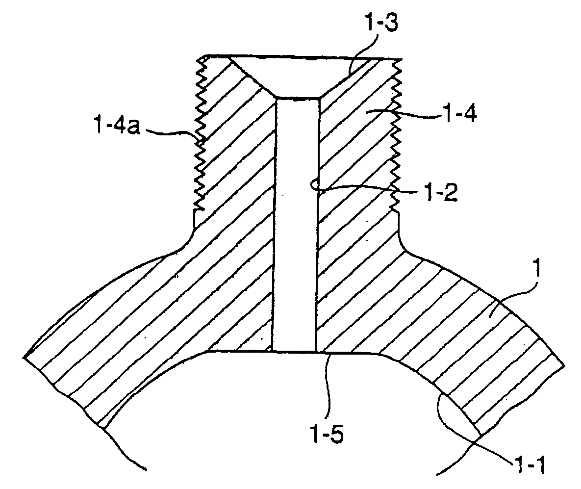
Figure 1 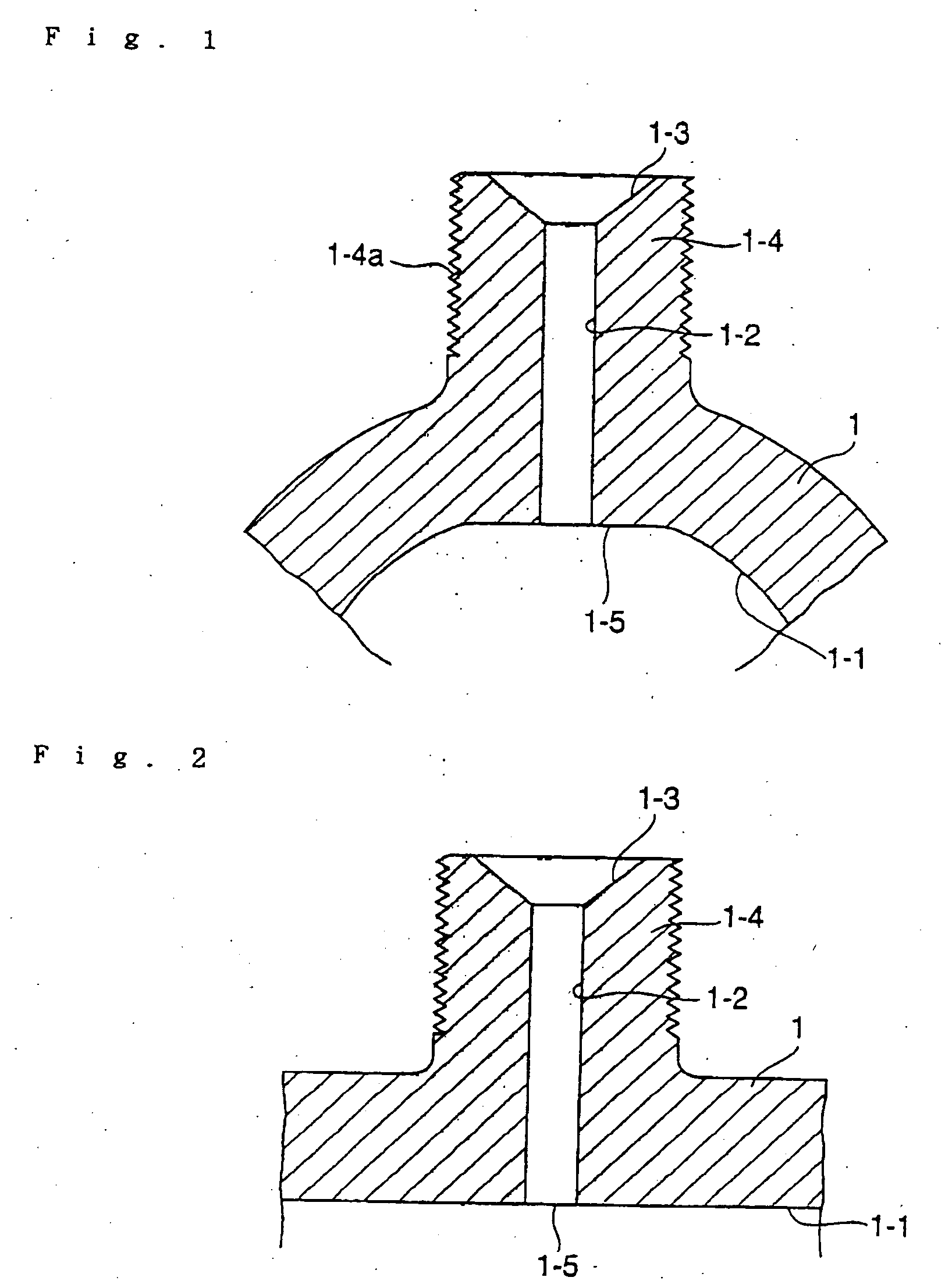
Figure 2 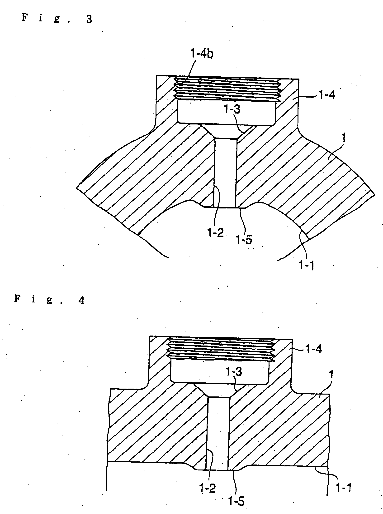
Figure 3
Abstract
Description
[0001] This application is a divisional U.S. patent application Ser. No. 10 / 653,477, filed Sep. 2, 2003.BACKGROUND OF THE INVENTION
[0002] 1. Field of the Invention
[0003] The present invention relates to a common rail, such as high-pressure fuel manifolds, block rails, or the like, in a fuel injection system for diesel engines, and more particularly, to a common rail for diesel engines, in which portions of a branch hole or holes on a main pipe rail and a whole inner peripheral surface of the main pipe rail are enhanced in fatigue strength for inner pressures.
[0004] 2. Description of the Related Art
[0005] A common rail in a fuel injection system for diesel engines is shown in FIG. 7, and has a circular main pipe 11. The main pipe 11 has an internal flow passage 11-1. A branch hole 11-2 is provided in a peripheral wall of the main pipe 11 and communicates to the internal flow passage 11-1. The branch hole 11-2 leads to an outwardly opened pressure-receiving seat surface 11-3. A cy...
Examples
Embodiment Construction
[0032] In the invention, reference numeral 1 denotes a main pipe rail, 1-1 a flow passage, 1-2 a branch hole, 1-3 a pressure-receiving seat surface, 1-4 a boss portion, 1-4a a male thread, 1-5 a flattened surface, 2 a branch pipe, 2-1 a flow passage, and 2-2 a projection.
[0033] The main pipe rail 1 or common rail shown in FIGS. 1 to 4 is a forging of a material S45C or the like. The main pipe rail 1 has a tubular portion, which is relatively thick-walled to have, for example, a diameter of 28 mm and a wall thickness 9 mm. An axial interior is subjected to machining, such as boring, gun drilling, or the like, to make the flow passage 1-1, and boss portions 1-4 are provided on a peripheral wall to be axially spaced from one another.
[0034] In the common rail shown in FIGS. 1 and 2, branch holes 1-2 having a predetermined diameter are formed in the boss portions 1-4 which are integral with the main pipe rail 1 The branch holes 1-2 communicate with the flow passage 1-1 of the main pipe...